The OBO Ion charging station – more than just a charging point
All technical details at a glance
Our OBO Ion charging station offers numerous intelligent, forward-looking features for efficiently charging your electric car. This includes two options for PV-optimised charging. Solar power from your PV system is used to charge your electric car. The OBO Ion Protect variants also feature integrated surge protection. Last but not least, the Ion charging station has different options for protecting the RS-485 section between the external controller and the charging station.
Read more about the technical options offered by the different charging station variants and get inspired to harness the full potential of your Ion charging station.
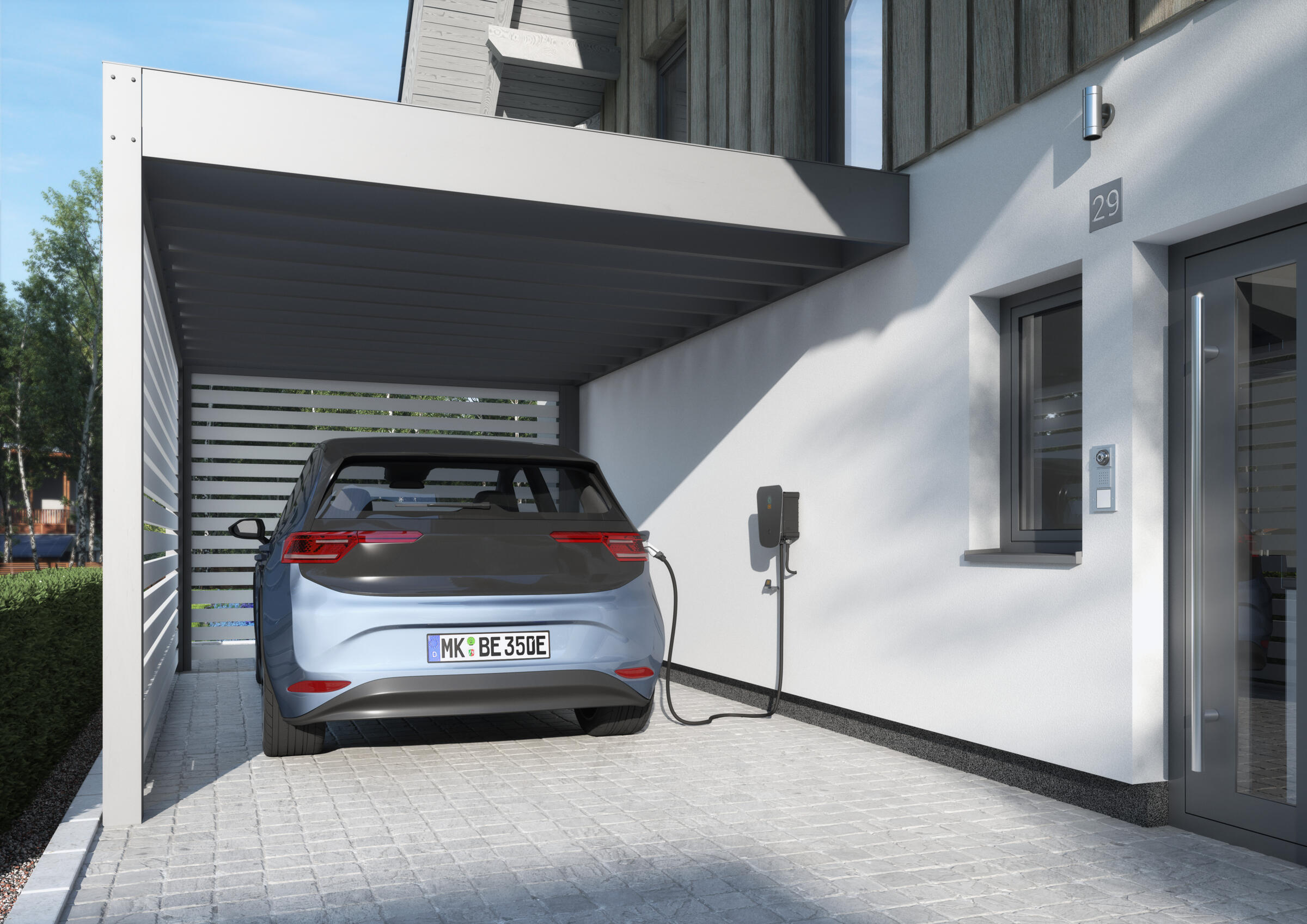
Charge electric vehicles sustainably and efficiently
Well-thought-out technology, simple mounting, tailor-made safety: The Ion charging station offers your customers two options for PV-optimised charging.
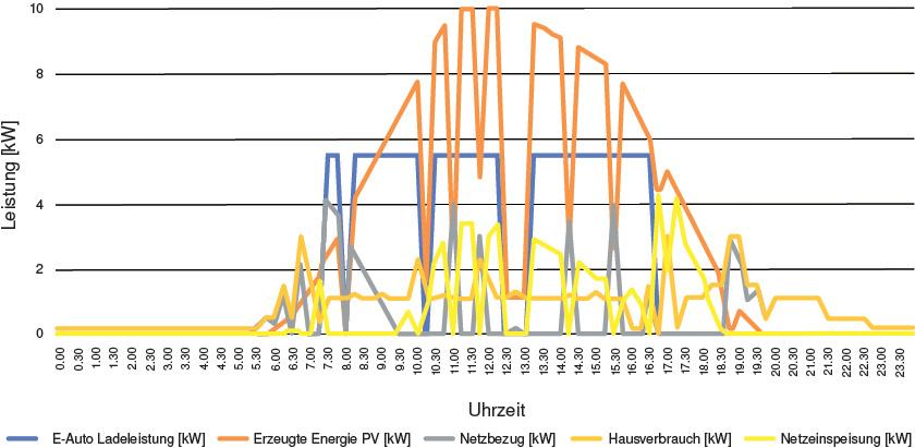
Static PV excess charging
With this variant, the charging operation of the OBO Ion charging station is controlled by an external unit, which sends an enabling signal from a previously defined PV excess-current level. These units include:
- Photovoltaic inverter
- Ripple control receiver
- Timer, key switch / numeric lock / RFID module
- Smart home technology
The loading operation switches on automatically during a PV current excess. If there is insufficient PV energy, the charging operation is automatically interrupted. If necessary, a series-connected external switch (e.g. IP44, wall-mounted) allows the switch-over to a charging operation, irrespective of the PV status, at any time.
Example with 10 kW AC solar power system (summer day)
| Charging into the car | 44 | kWh |
| Pure PV component: | 36.025 | kWh |
| Autarchy | 81.87 | per cent |
| Charging time | 9.25 | H |
| Charging power | 5.5 | kW |
Benefits of static PV excess-current charging
- Increase in autarchy by plus 10% to 15%
- Financial implementation costs
- Refittable in a simple and uncomplicated manner
- Compatibility with different inverters/smart meters
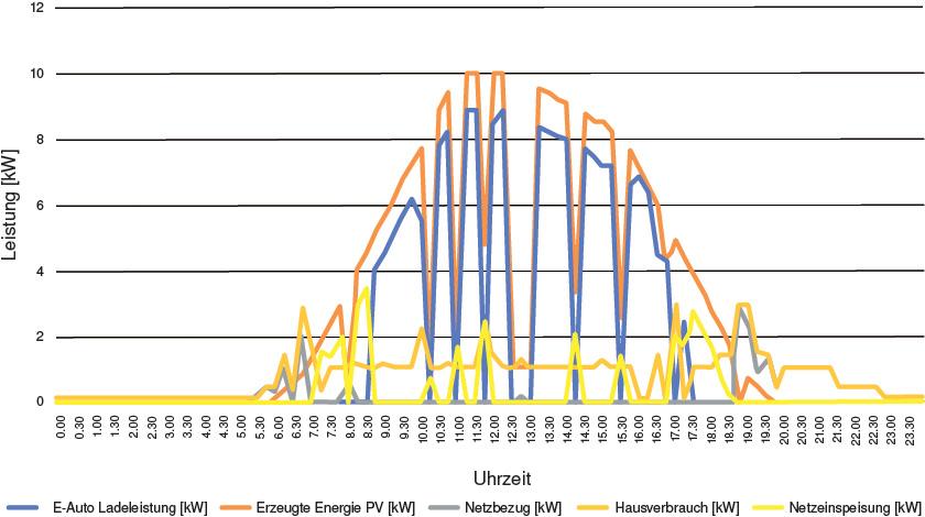
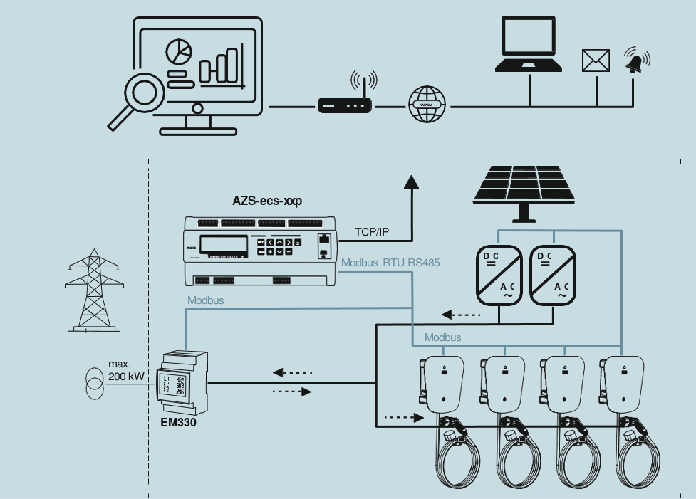
Dynamic PV excess-current charging
The Ion charging station can be dynamically activated directly via external Modbus RTU 485 controllers. This means that the following functions can be controlled, amongst others:
- PV excess-current charging
- Dynamic load management
- Digital authentication via web or app
| Charging into the car | 44 | kWh |
| Pure PV component | 41.15 | kWh |
| Autarchy | 93.52 | per cent |
| Charging time | 8.5 | H |
| Charging power | Up to 9 | kW |
Benefits of dynamic PV excess-current charging
- Maximum autarchy up to plus 30%
- Multiple charging programs selectable
- Can be used digitally via web or app management
- Refittable in a simple and uncomplicated manner
- Compatible with various EMS devices
In conjunction with the optional EMS device, the loading operation switches on automatically during a PV current excess and can be adapted in an optimised manner. If there is insufficient PV energy, charging is regulated automatically and interrupted. The programming and setting of the charging times can be carried out individually.
Here, surge protection is already integrated: The Ion Protect version of the charging station
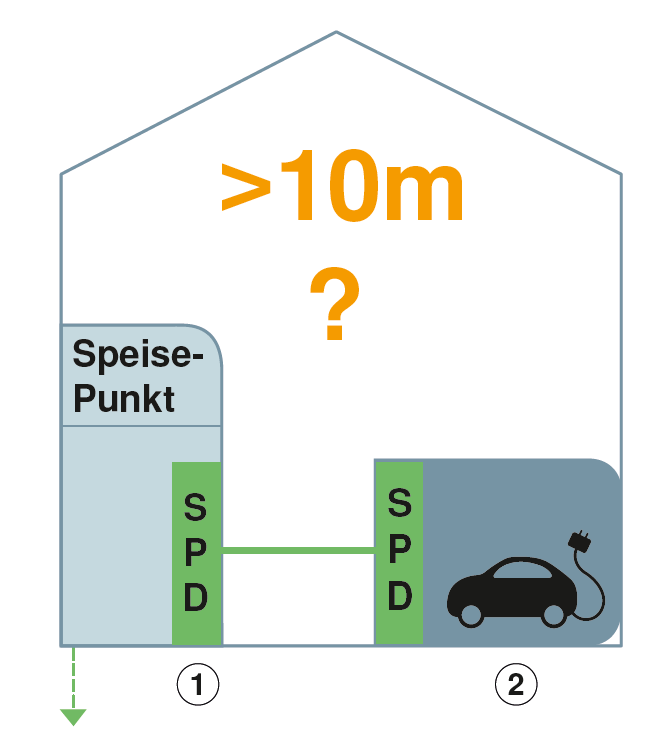
The VDE 0100-443 standard demands the presence of surge protection. If none exists in the building, at least one type 2 SPD must be erected at the infeed point of the system during the creation of a new circuit. With cable lengths of over ten metres, additional surge protection is recommended on the charging unit, which protects both the charging station and the electric vehicle. Surge protection also applies for the data cable connection between the charging station and, for example, the PV system between the charging station and electric vehicle.
With the Ion charging station, you can meet all these requirements in a simple manner: The Ion Protect version of the charging station has integrated standardised complete surge protection. This is only available from OBO.
To protection current infeed: surge protective device compact module, type 2+3
- Surge protection in sub-distributors according to VDE 0100- 443 (IEC 60364- 4- 44)
- Arresting capacity up to 60 kA (8/20) in total
- Integrated 3+1 solution for TN and TT network systems at 45 mm module width
- High-performance varistor systems
- Including thermal and dynamic separating device and visual function display
Protection of the RS-485 section
Two different options are available for the protection of the RS-485 section between the external controller and charging station (Modbus RTU):
Series protection device, 2-pin, 12 V version
Lightning barrier with test function, 12 V version
- Nominal load current 10 A
- Protective device for multi-wire systems
- Direct shield earthing and with screwless connection terminals
- Space-saving width of just 8.7 mm
- Testable protection circuit with Life Control
- High bandwidth up to 100 MHz
Series protection device, 2-pin, 5 V version
Lightning barrier with test function, 5 V version
- Nominal load current 0.58 A
- Protective device for multi-wire systems
- Direct shield earthing and with screwless connection terminals
- Space-saving width of just 8.7 mm
- Testable protection circuit with Life Control
- High frequency range of 0–100 MHz
Model overview and equipment
| Component | 6570020 | 6570022 | 6570024 | 6570026 | |
Ion charging station Basic | Ion charging station Key | Ion charging station Basic Protect | Ion charging station Key Protect | ||
| 1 | Front panel | ||||
| 2 | Charging station status LED | ||||
| 3 | Surge protection Status LED | X | X | ||
| 4 | On/off switch without authorisation | X | X | ||
On/off switch with authorisation (key switch) | X | X | |||
| 5 | Charging connector, type 2 | ||||
| 6 | Wall bracket, charging cable | ||||
| 7 | Charging cable, 5 m | ||||
| 8 | Cable entry for supply cable | ||||
| 9 | Ion charging station power plate with QR code | ||||
| 10 | Charging controller, Mode 3 | ||||
| 11 | Fuse 1 A 250 VAC 5x20 | ||||
| 12 | Surge protection V10 Compact energy technology | X | X | ||
| 13 | Installation protection | ||||
| 14 | Error current monitoring DC | ||||
| 15 | Connection terminals | ||||
| 16 | Surge protection Data technology MDP 5 V | X | X | ||
| 17 | Surge protection Data technology MDP 12 V | X | X |