Determining the wind load
With the detailed instructions from OBO, you can easily calculate the wind load and effects on buildings and systems. Try it out now.
We at OBO Bettermann have extensive expertise in the area of wind loads in relation to external lightning protection. Today’s calculation models and air-termination rod systems are the result of numerous studies and years of R&D experience.
The previous German standards in this area – DIN 1055:2005 Part 4: Wind loads and Part 5: Snow and ice loads, and DIN 4131: Steel antenna mounts – dealt with all load assumptions for mounts in Germany.
The Eurocodes (EC) are the result of European standardisation in the construction field. EC 0 to EC 9 cover the documents in the series DIN EN 1990 to 1999. These are supplemented by the various national annexes (NA). The NAs contain provisions that go beyond the Eurocode rules, i.e. the provisions that were previously part of the national standards.
Following the publication of the national annexes to the ECs, the old standards became invalid, following appropriate coexistence phases.

Example of German national standards for the calculation of wind load
| Old standard | New standard |
| DIN 1055:2005-03 Part 4: Wind loads | Eurocode 1: DIN EN 1991-1-4:2010-12: Parts 1–4: General effects; wind loads + DIN EN 1991-1-4/NA: 2010-12 |
| DIN 1055:2005-03 Part 5: Snow and ice loads | DIN EN 1991-1-3: 2010-12 -; Parts 1–3: General effects; snow loads + DIN EN 1991-1-3/NA: 2010-12 |
| DIN V 4131:2008-09 Steel antenna mounts | Eurocode 3: DIN EN 1993-3-1: 2010-12: Parts 3-1: Towers, masts and chimneys – Towers and masts + DIN EN 1993-3-1/NA: 2010-12 |
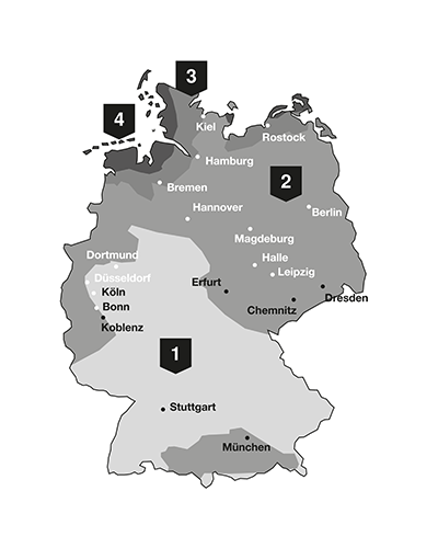
1st step: Determining the wind zone
The second factor that needs to be known when determining the wind load is the wind load zone in which the object is located.
The standards contain no statements regarding the following aspects:
- Framework masts and towers with non-parallel main legs,
- Stayed masts and chimneys,
- Cable-stayed and suspension bridges,
- Torsional vibrations.
| Zone | Wind speed in m/s | Speed pressure in kN/m² |
| 1 | 22.5 | 0.32 |
| 2 | 25.0 | 0.39 |
| 3 | 27.5 | 0.47 |
| 4 | 30.0 | 0.56 |
2nd step: Determining the terrain category (TC)
Terrain-specific loads and dynamic pressures are an important element in calculating wind loads.
Terrain categories according to DIN EN 1991-1-4
| Terrain category (TC) | Definition |
| Terrain category I | Open sea; lakes with at least 5 km of open water in the wind direction; even, flat land without obstacles |
| Terrain category II | Terrain with hedges, individual farmsteads, buildings or trees, e.g. agricultural area |
| Terrain category III | Suburbs, industrial or commercial areas; forests |
| Terrain category IV | Urban areas in which at least 15% of the area is built up with buildings whose average height is higher than 15 m |
3rd step: Determining the maximum gust speed
The tilt and slip resistance of air-termination rods must always be determined on a project-by-project basis. The reference height is the building height and two thirds of the length of the air-termination rod. The maximum gust speed at the project location must be determined.

Gust speed in wind zone I
| Reference height in metres | TC I in kph | TC II in kph | TC III in kph | TC IV in kph |
| 0 | 112 | 105 | 100 | 93 |
| 5 | 122 | 108 | 100 | 93 |
| 10 | 136 | 124 | 103 | 93 |
| 16 | 136 | 124 | 111 | 93 |
| 20 | 139 | 128 | 115 | 98 |
| 30 | 145 | 134 | 122 | 106 |
| 40 | 149 | 139 | 128 | 112 |
| 70 | 157 | 148 | 139 | 126 |
| 100 | 162 | 155 | 147 | 135 |
Gust speed in wind zone II
| Reference height in metres | TC I in kph | TC II in kph | TC III in kph | TC IV in kph |
| 0 | 124 | 117 | 111 | 104 |
| 5 | 136 | 120 | 111 | 104 |
| 10 | 145 | 131 | 114 | 104 |
| 16 | 152 | 138 | 123 | 104 |
| 20 | 155 | 142 | 127 | 109 |
| 30 | 161 | 149 | 136 | 118 |
| 40 | 165 | 154 | 142 | 125 |
| 70 | 174 | 165 | 155 | 139 |
| 100 | 180 | 172 | 163 | 150 |
Gust speed in wind zone III
| Reference height in metres | TC I in kph | TC II in kph | TC III in kph | TC IV in kph |
| 0 | 137 | 129 | 122 | 114 |
| 5 | 149 | 132 | 122 | 114 |
| 10 | 159 | 144 | 126 | 114 |
| 16 | 167 | 152 | 135 | 114 |
| 20 | 170 | 156 | 140 | 119 |
| 30 | 177 | 164 | 149 | 129 |
| 40 | 182 | 170 | 156 | 137 |
| 70 | 192 | 181 | 170 | 153 |
| 100 | 198 | 189 | 180 | 165 |
Gust speed in wind zone IV
| Reference height in metres | TC I in kph | TC II in kph | TC III in kph | TC IV in kph |
| 0 | 149 | 140 | 133 | 124 |
| 5 | 163 | 144 | 133 | 124 |
| 10 | 174 | 157 | 137 | 124 |
| 16 | 182 | 166 | 148 | 125 |
| 20 | 186 | 170 | 153 | 130 |
| 30 | 193 | 179 | 163 | 141 |
| 40 | 198 | 185 | 170 | 150 |
| 70 | 209 | 198 | 185 | 167 |
| 100 | 216 | 206 | 196 | 180 |
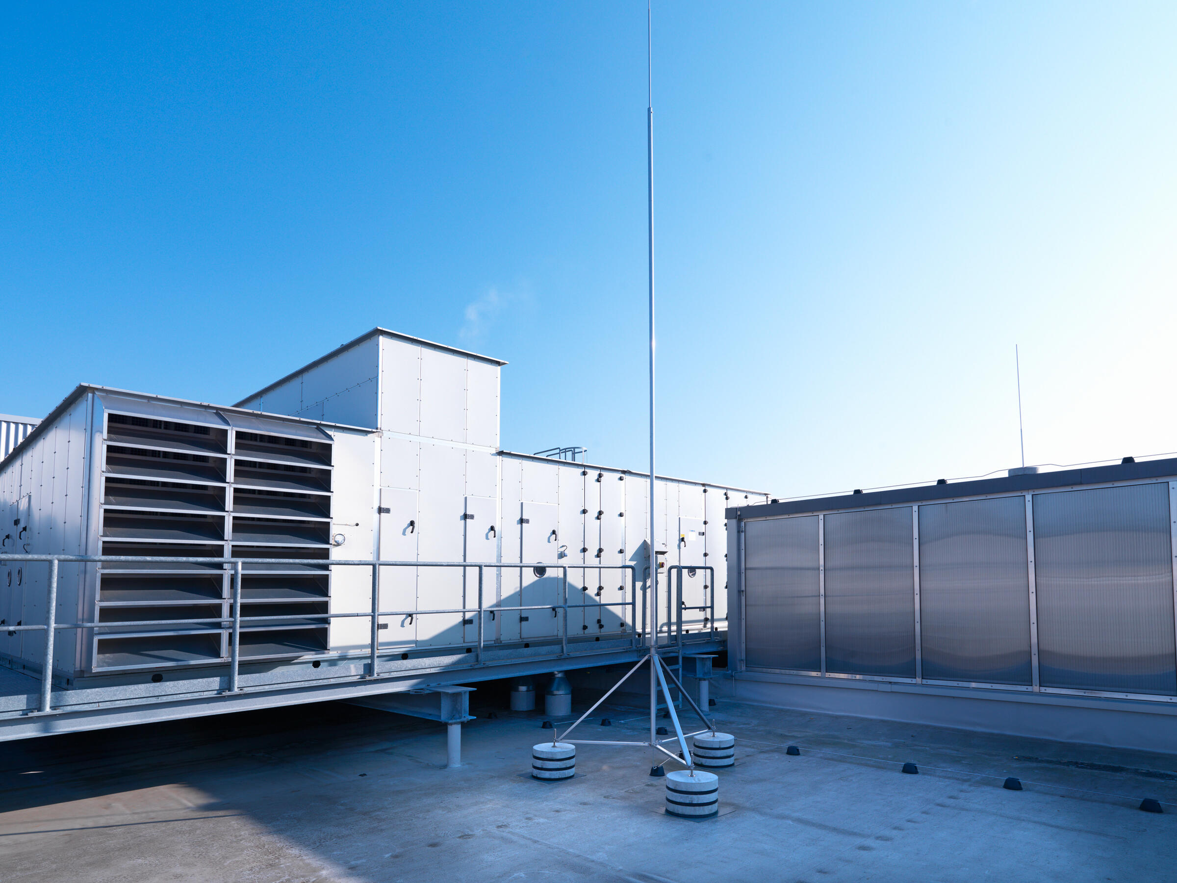
4th step: Determining what concrete blocks are required
Based on the maximum gust speed, the number and size (10 or 16 kg) of concrete blocks required can be determined for the air-termination rod used. The value in the tables must lie above the maximum gust speed for the location.
An example
The maximum gust speed at the location is 142 km/h.
A tapered pipe air-termination rod of type 101 VL2500 and a height of 2.5 m is used.
Because the value in Table 2.15 must be higher than the maximum gust speed at the location (i.e. in this case more than 142 km/h), the next possible value is 164. Three concrete blocks, each of weight 16 kg, must therefore be used.
Number of concrete blocks for tapered pipe air-termination rods
| Air-termination rod height in m | 1.5 | 2 | 2.5 | 3 | 3.5 | 4 | Required concrete blocks |
| Type | 101 VL1500 | 101 VL2000 | 101 VL2500 | 101 VL3000 | 101 VL3500 | 101 VL4000 | |
| Item no. | 5401 98 0 | 5401 98 3 | 5401 98 6 | 5401 98 9 | 5401 99 3 | 5401 99 5 | |
| Wind speed kph | 117 | - | - | - | - | - | 1x 10 kg |
| Wind speed kph | 164 | 120 | 95 | - | - | - | 2x 10 kg |
| Wind speed kph | 165 | 122 | 96 | - | - | - | 1x 16 kg |
| Wind speed kph | - | 170 | 135 | 111 | 95 | - | 2x 16 kg |
| Wind speed kph | - | 208 | 164 | 136 | 116 | 102 | 3x 16 kg |
Number of concrete blocks for air-termination rod, one end rounded
| Air-termination rod height in m | 1 | 1.5 | 2 | 2.5 | 3 | Required concrete blocks |
| Type | 101 ALU-1000 | 101 ALU-1500 | 101 ALU-2000 | 101 ALU-2500 | 101 ALU-3000 | |
| Item no. | 5401 77 1 | 5401 80 1 | 5401 83 6 | 5401 85 2 | 5401 87 9 | |
| Wind speed kph | 97 | - | - | - | - | 1x 10 kg |
| Wind speed kph | 196 | 133 | 103 | - | - | 1x 16 kg |
| Wind speed kph | - | 186 | 143 | 117 | 100 | 2x 16 kg |
| Wind speed kph | - | - | 173 | 142 | 121 | 3x 16 kg |
Number of concrete blocks for air-termination rod, one end rounded with connection strap
| Air-termination rod height in m | 1 | 1.5 | Required concrete blocks |
| Type | 101 A-L 100 | 101 A-L 150 | |
| Item no. | 5401 80 8 | 5401 85 9 | |
| Wind speed kph | 100 | - | 1x 10 kg |
| Wind speed kph | 192 | 129 | 1x 16 kg |
| Wind speed kph | - | 177 | 2x 16 kg |
| Wind speed kph | - | 214 | 3x 16 kg |
Number of concrete blocks for insulated VA and Al air-termination rods
| Air-termination rod height in m | 4 | 6 | 4 | 6 | Required concrete blocks |
| Material | VA | VA | Al | Al | |
| Item no. | 5408 94 2 | 5408 94 6 | 5408 94 3 | 5408 94 7 | |
| Item no. of appropriate air-termination rod stand | 5408 96 8 | 5408 96 9 | 5408 96 6 | 5408 96 7 | |
| Wind speed kph | 120 | 94 | 120 | 92 | 3x 16 kg |
| Wind speed kph | 161 | 122 | 163 | 122 | 6x 16 kg |
| Wind speed kph | 194 | 145 | 197 | 147 | 9x 16 kg |
| Wind speed kph | 222 | 165 | 227 | 168 | 12x 16 kg |
| Wind speed kph | 246 | 182 | 252 | 187 | 15x 16 kg |
Number of concrete blocks for insulated air-termination rods with exit
| Air-termination rod height in m | 4 | 6 | 8 | 10 | Required concrete blocks |
| Item no. | 5408 93 8 | 5408 94 0 | 5408 88 8 | 5408 89 0 | |
| Item no. of appropriate air-termination rod stand | 5408 93 0 | 5408 93 2 | 5408 90 2 | 5408 90 2 | |
| Wind speed kph | 110 | 85 | 93 | 82 | 3x 16 kg |
| Wind speed kph | 148 | 111 | 116 | 102 | 6x 16 kg |
| Wind speed kph | 178 | 132 | 134 | 119 | 9x 16 kg |
| Wind speed kph | 204 | 151 | 151 | 133 | 12x 16 kg |
| Wind speed kph | 227 | 167 | 166 | 146 | 15x 16 kg |
Number of concrete blocks for isFang air-termination rod with VA tripod
| Air-termination rod height in m | 4 | 4.5 | 5.0 | 5.5 | 6.0 | 6.5 | 7.0 | 7.5 | 8.0 | Required concrete blocks |
| Item no. of air-termination rod | 5402 86 4 | 5402 86 6 | 5402 86 8 | 5402 87 0 | 5402 87 2 | 5402 87 4 | 5402 87 6 | 5402 87 8 | 5402 88 0 | |
| Item no. of appropriate air-termination rod stand | 5408 96 8 | 5408 96 8 | 5408 96 8 | 5408 96 8 | 5408 96 9 | 5408 96 9 | 5408 96 9 | 5408 96 9 | 5408 96 9 | |
| Wind speed kph | 143 | 124 | 110 | 99 | 104 | 96 | 89 | 83 | 78 | 3x 16 kg |
| Wind speed kph | 193 | 168 | 148 | 133 | 138 | 127 | 117 | 109 | 102 | 6x 16 kg |
| Wind speed kph | 232 | 202 | 178 | 159 | 165 | 151 | 139 | 129 | 121 | 9x 16 kg |
| Wind speed kph | 266 | 231 | 203 | 182 | 188 | 172 | 159 | 147 | 138 | 12x 16 kg |
| Wind speed kph | 296 | 257 | 226 | 202 | 208 | 191 | 176 | 163 | 152 | 15x 16 kg |