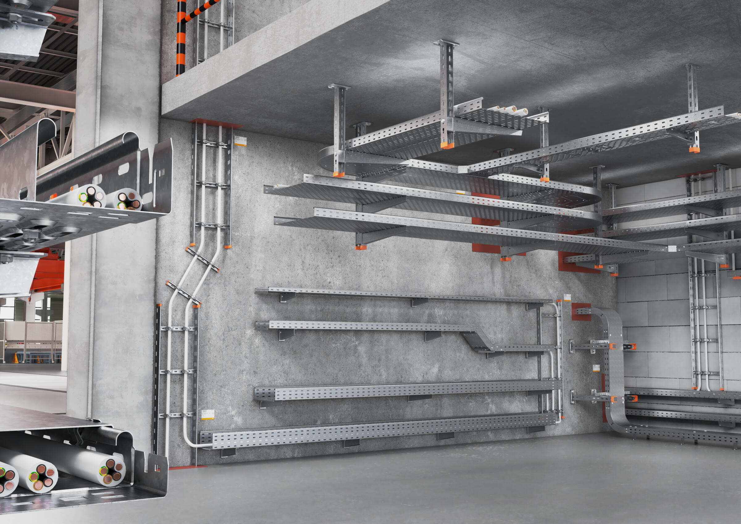
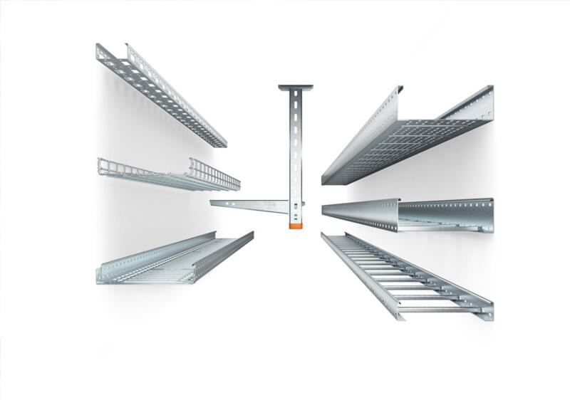
Design and functional features of cable support systems
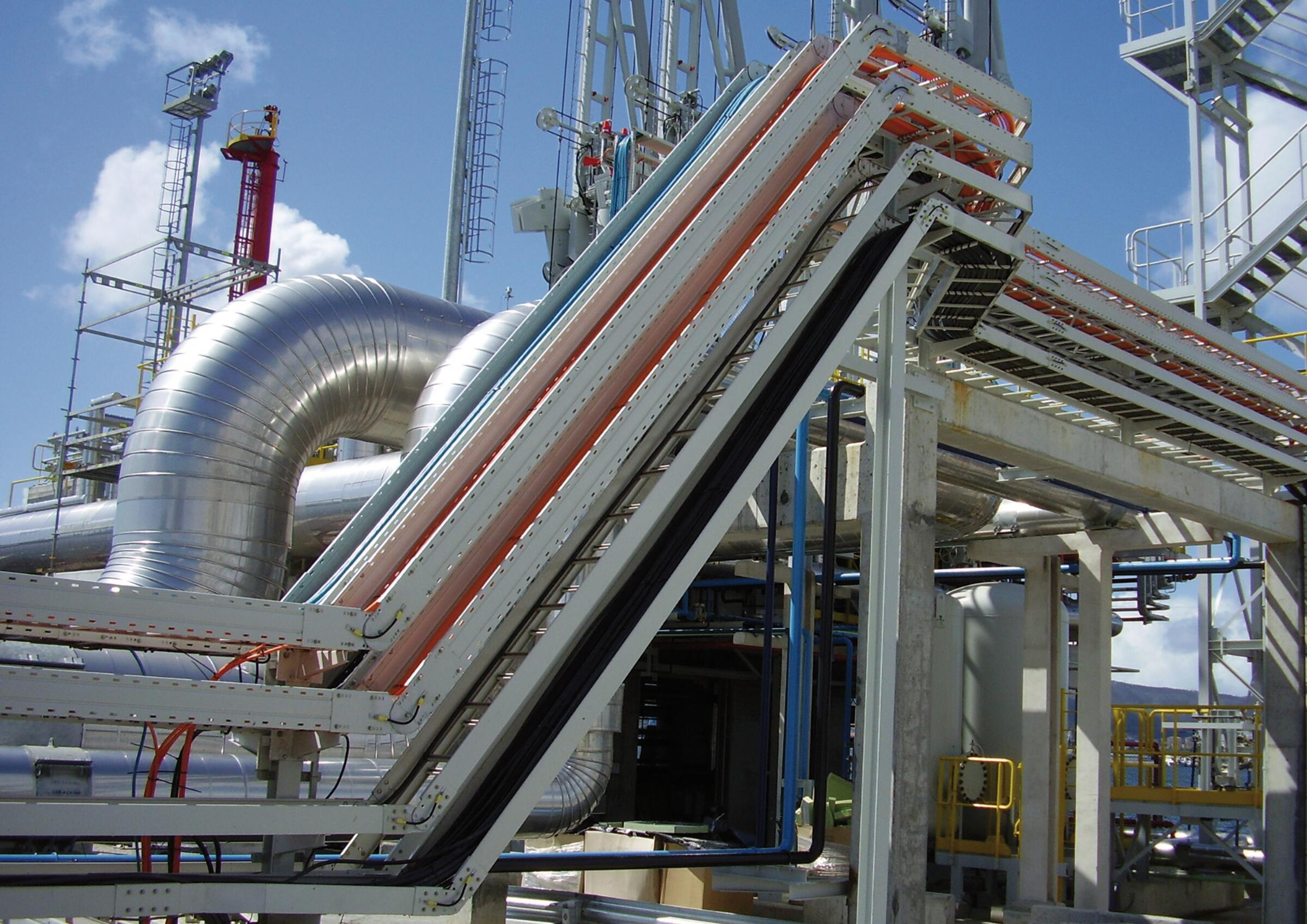
Cable support systems are essential components of a safe and efficient electrical installation. They are used not only for tidy cable routing and fastening, but also have to withstand a wide range of mechanical and environmental loads. The selection of the correct system is dependent on various factors, such as material, corrosion resistance and operating environment. We will explain the most important design and functional properties of cable support systems – from the materials used, to surface coatings through to corrosion protection measures.
FAQ – cable support system basics
What is a cable support system?
Where are cable support systems installed?
What materials are cable support systems made of?
What components does a cable support system have?
What different cable support systems are there?
What are fittings for?
What are support elements?
What are mounting elements used for?
What accessory parts are available?
What is the support distance?
Are external fastening elements part of the cable support system?
Corrosion and corrosion protection
Generally, a distinction is made between the following corrosion mechanisms:
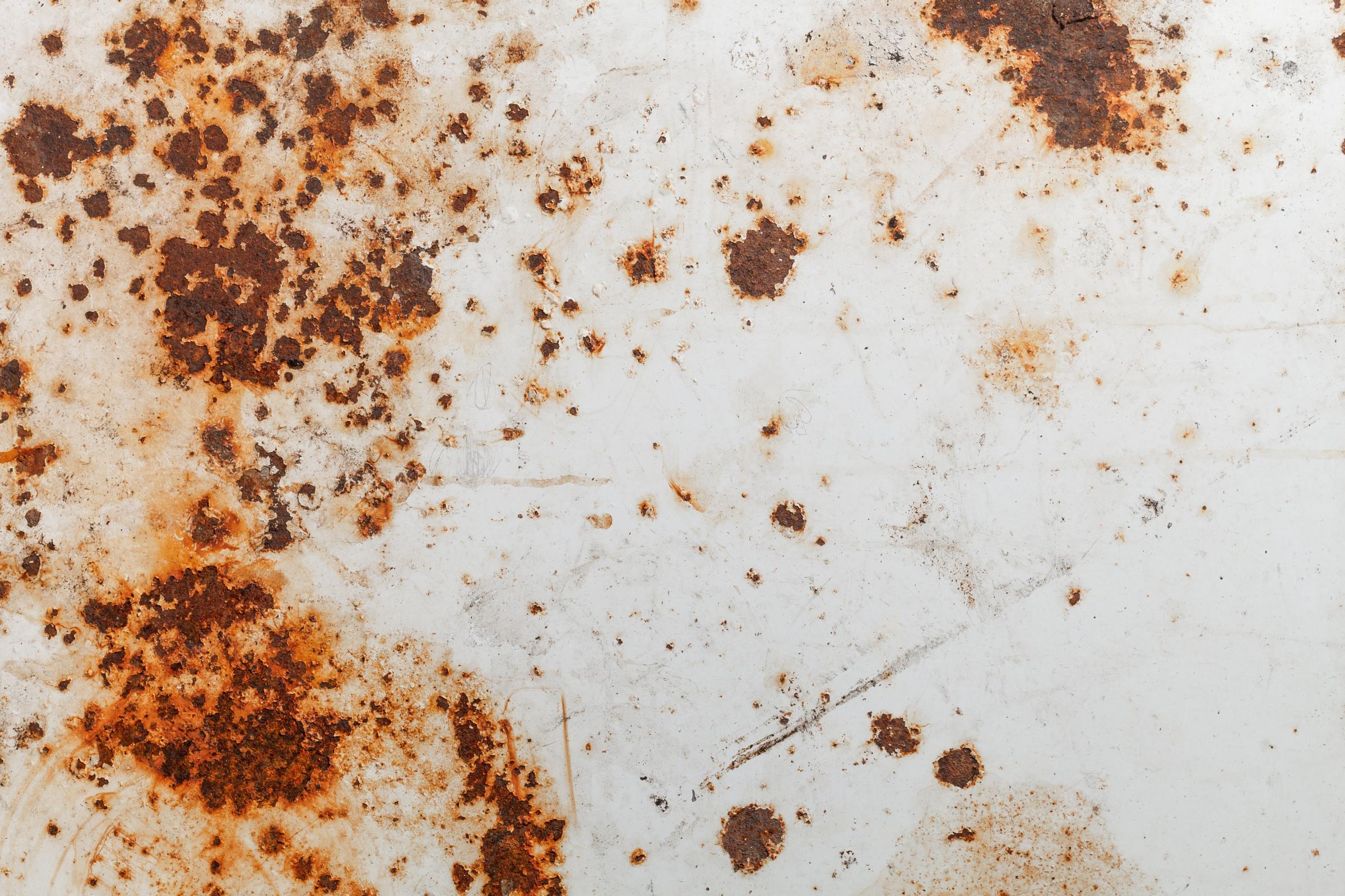
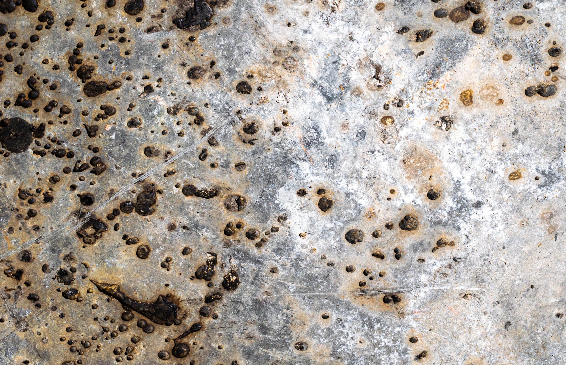
Surface corrosion
- Unprotected, unalloyed steel oxidises extensively due to moisture and oxygen
- Classic rust formation on steel
- If the rust formation location is limited, then this is termed hole or sink corrosion
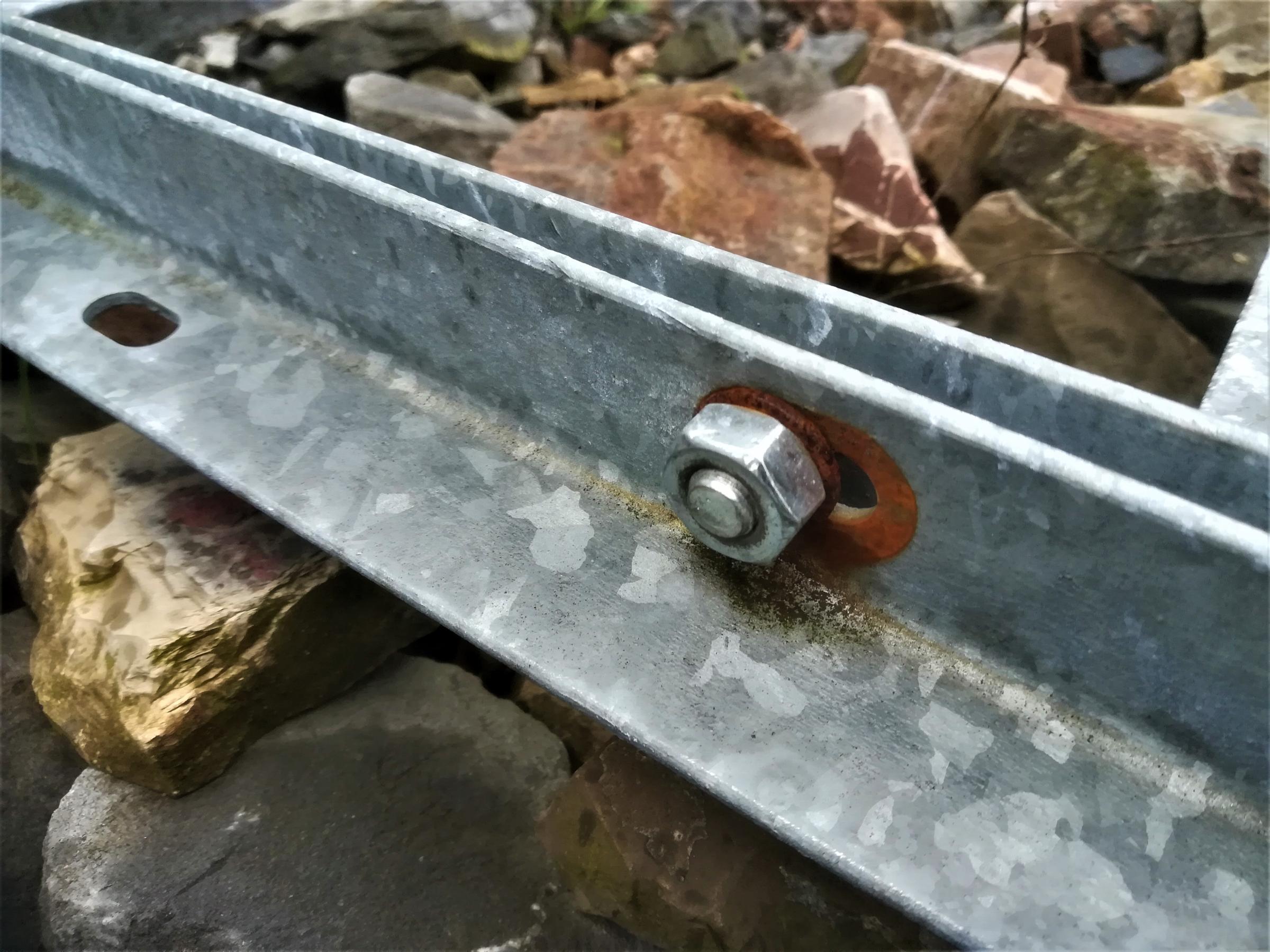
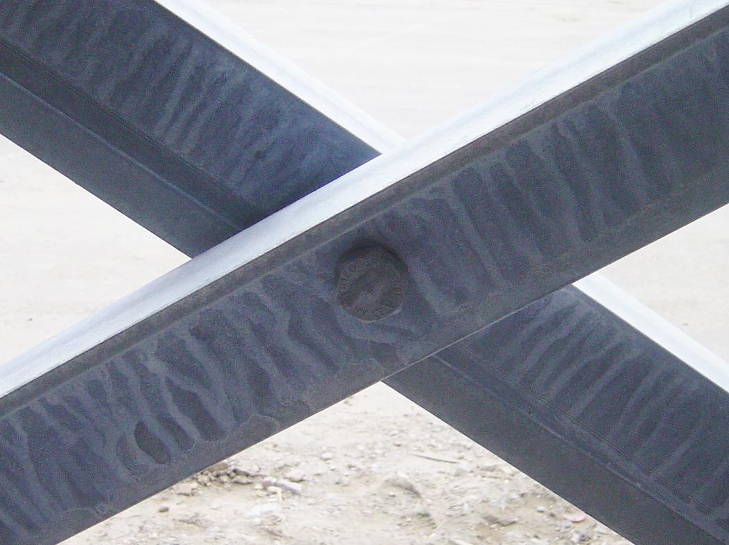
Contact or bi-metallic corrosion
- Caused by the different electrochemical potentials of two metals (e.g. zinc and VA)
- Difference between precious metals and base metals
- Precious metals: electrochemical potential > 0
- Base metals: electrochemical potential < 0
- The baser partner oxidises
- Observe the area rule:
- Good ratio: base large, precious small
- Poor ratio: precious large, base small
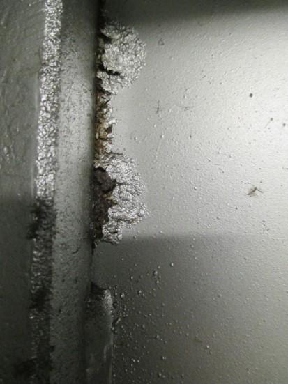
Gap corrosion
- This affects unalloyed steel and stainless steel (this also applies if the gap is caused by plastic on steel)
- Caused by moisture in narrow gaps (< 1 mm)
- The electrolyte in the gap “acidifies” (i.e. the pH value falls), the electrolyte on the outside becomes alkaline (i.e. the pH value increases)
- Reaction products form, which can finally be seen as rust, hollowing out the gap
Hole corrosion on stainless steels
- Passive layer of the stainless steels is harmed, due primarily to chloride
- Local spot corrosion can form, which hollows out the steel at the appropriate point
- In addition, tension crack corrosion can occur if there are tensions in the material (material cracks along the grain borders)
Corrosion of galvanisations
- Zinc uses carbon from the air to form a protective zinc carbonate covering layer after a few days
- If the zinc surface is exposed to moisture, then white rust will form before the covering layer can form
- Zinc is particularly prone to corrosion if salts exist (usually chloride, sulphate). This causes the zinc to be removed very quickly, meaning that the steel is unprotected
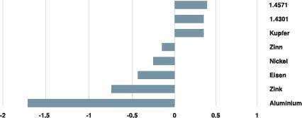
Electrochemical series of the metals
| small/large | Zn (FS and FT) | AI | Cu | VA | CuZn |
|---|---|---|---|---|---|
| Zn (FS and FT) | x | x | |||
| AI | x | x | |||
| Cu | |||||
| VA | |||||
| CuZn |
- Moderate to no corrosion
- Moderate corrosion
x Heavy corrosion
The precondition for corrosion is a conductive medium that connects the metal combination. The more damp and contaminated the atmosphere is, the more pronounced the contact corrosion.
Surfaces
G | FS | FT/(DD) |
Electrogalvanised | Hot galvanised | Hot-dip galvanised/(Double Dip) |
Materials
A2 | A4 | A5 |
Stainless steel | Stainless steel | Stainless steel |
Special solutions (on request)
FTSO | FSK/FTK |
Special layer thickness | Plastic coating |
Surfaces
The following galvanisation surfaces can be applied to improve corrosion protection:
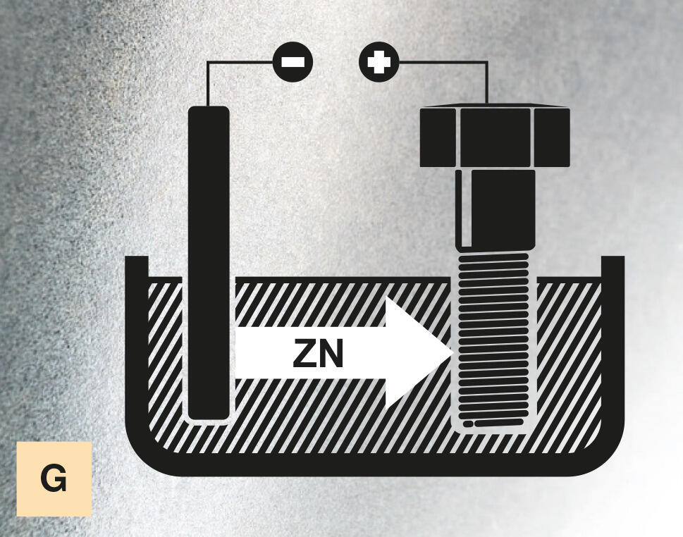
Galvanisation
- Application of the zinc covering using an electrolysis method (direct current)
- Normal layer thicknesses, approx. 5–15 μm
- Retreatment normally in the form of passivation and/or sealing
Standards: DIN EN ISO 19598 & DIN EN ISO 4042
Applications: Indoor areas without harmful substances, e.g. offices, sales rooms – corrosivity category according to DIN EN ISO 12944-2: C1
Examples: Mesh cable trays and connection elements
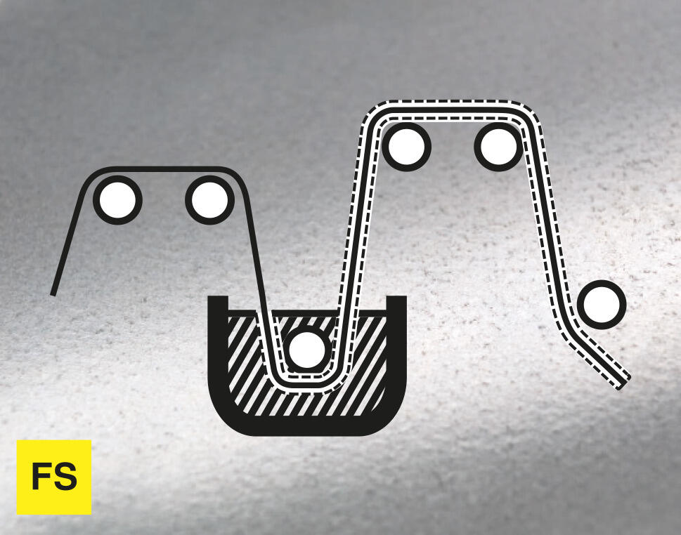
Strip galvanisation
- During the strip galvanisation process, also termed sendzimir galvanisation, the steel strip is galvanised in a continuous process
- Materials: DX51D
- Normal layer thicknesses (Z 275) approx. 13–27 μm
- Retreatment of the coil possible in the form of passivation and/or sealing
Standards: DIN EN 10346
Applications: Indoor areas in which condensation can occur, e.g. sports halls or warehouses – corrosivity category according to DIN EN ISO 12944-2: Up to C2
Examples: Cable trays, covers
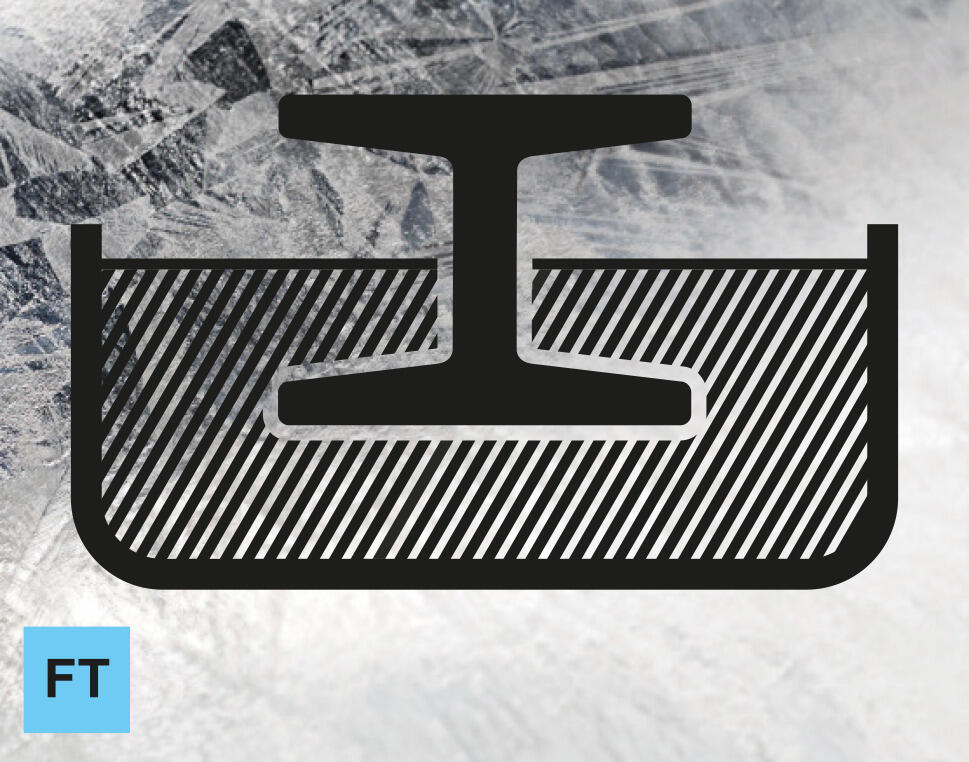
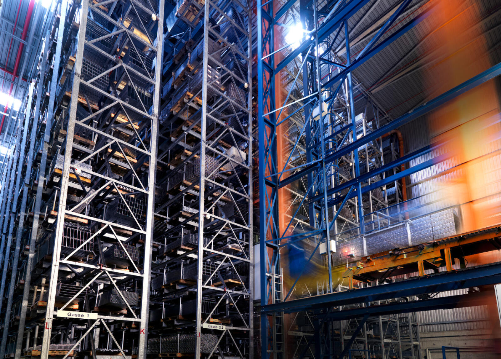
Hot-dip galvanisation
- The fully formed product is coated using a dipping method
- Materials: C9D, DC01, DD11, S235JR
- Normal layer thicknesses, approx. 45–85 μm
Standards: DIN EN ISO 1461
Applications: Indoor areas with a certain level of moisture and impurity, outdoor areas with medium levels of contamination, e.g. laundries, urban atmosphere – corrosivity category according to DIN EN ISO 12944-2: To C3 (depending on layer thickness, up to C4)
Examples: Cable ladders, mesh cable trays, suspended supports and brackets
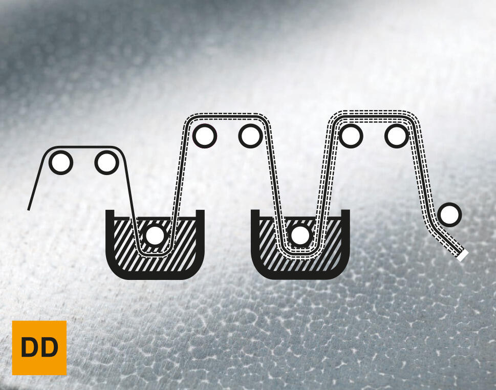
Hot-dip coating (Double Dip)
- Zinc-aluminium coating according to DIN EN 10346
- The material to be galvanised then passes through two baths: The first contains pure zinc, the second a zinc-aluminium alloy
Standards: DIN EN 10346
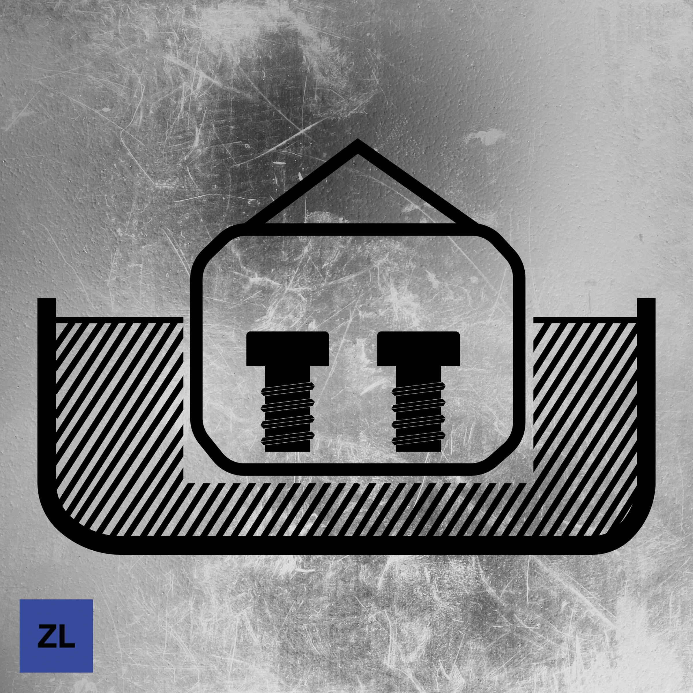
Zinc slat coating
- Processing of untreated steel to small parts, such as screws or washers
- Subsequent coating in the immersion spinning method, with an anorganic, zinc and aluminium-rich substance
- Layer thickness: 5–20 µm
- Cathodic corrosion protection allows small scratches, e.g. due to transport or mounting
Standards: DIN EN 13858, DIN EN ISO 10683
Applications: Interior, exterior
Examples: Connection elements, fastening elements
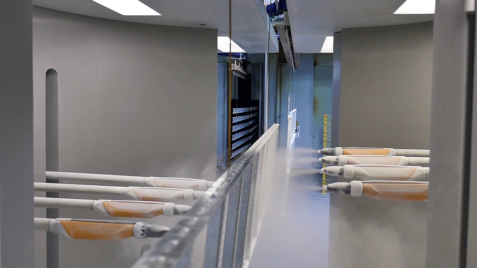
Plastic coating
- Plastic coating through electrostatically charged plastic powder
- Coating for reasons of corrosion protection or for decorative reasons
- Particularly good adhesion through pretreatment of the components with different fluids
- Plastic powder made of epoxy and/or polyester resins, as well as polyurethane
- Normal layer thicknesses, approx. 70–100 μm
- Coating of various system components possible with the following surfaces:
- Strip galvanised (FS) and hot-dip galvanised (FT)
- Electrogalvanised (G) and aluminium (Al)
Standards: DIN 55633/55634
Corrosion protection applications:
- Hot-dip galvanised system components with coating (Duplex)
- Very resistant to moisture, impurities and chemical influences
- Buildings with continuous condensate formation and strong impurities
- Corrosivity category according to DIN EN ISO 12944-2: Up to C5
Decorative reasons:
- Special visual requirements, appropriate to the colour design of the structure
- Coloured separation or assignment of different functions
- Available in all RAL colours
Materials
Stainless/rustproof steel
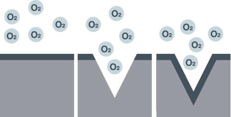
- The entry of oxygen causes a chromium oxide layer to form (passive layer), which protects against corrosion
- If the passive layer is damaged, e.g. by cutting, it forms again through further entry of oxygen
- Materials according to the alloy composition:
- A2:
- 1.4301 (AISI 304)
- 1.4303 (AISI 305/308)
- 1.4310 (AISI 301)
- 1.4567 (AISI 304Cu)
- A4:
- 1.4401 (AISI 316)
- 1.4404 (AISI 316L)
- 1.4435 (AISI 316L)
- 1.4571 (AISI 316Ti)
- 1.4578
- A5:
- 1.4529
- 1.4547
- 1.4462
- A2:
- Standard: EN 10088
- Corrosivity category according to DIN EN ISO 12944-2:
- A2: to C3
- A4: to C5
- A5: to CX
- Overview of key alloy elements
| Element | Properties in the steel |
| Nickel |
|
| Molybdenum |
|
| Titanium |
|
| Nitrogen |
|
Corrosivity categories according to DIN EN ISO 12944-2:2018
| Corrosivity category | Mass loss/thickness reduction relative to the area (after the first year of warehouse removal) | Example of typical environments (only for information purposes) | ||||
|---|---|---|---|---|---|---|
Unalloyed steel | Zinc | Open air | Interior | |||
| Mass loss g/m² | Thickness reduction µm | Mass loss g/m² | Thickness reduction µm | |||
| C1 negligible | ≤ 10 | ≤ 1.3 | ≤ 0.7 | ≤ 0.1 | – | Heated building with neutral atmosphere, e.g. offices, sales areas, schools, hotels |
| C2 low | > 10 to 200 | > 1.3 to 25 | > 0.7 to 5 | > 0.1 to 0.7 | Atmosphere with low degree of impurity: Usually rural areas | Unheated buildings, in which condensation can occur, e.g. warehouses, sports halls |
| C3 medium | > 200 to 400 | > 25 to 50 | > 5 to 15 | > 0.7 to 2.1 | Urban and industrial atmosphere with medium sulphur dioxide load; and coastal atmosphere with low salt load | Production rooms with high humidity and a certain amount of air impurities, e.g. food processing plants, laundries, breweries, dairies |
| C4 heavy | > 400 to 650 | > 50 to 80 | > 15 to 30 | > 2.1 to 4.2 | Industrial atmosphere and coastal atmosphere with medium salt load | Chemical plants, shipyards near the coast and harbours |
| C5 very heavy | > 650 to 1,500 | > 80 to 200 | > 30 to 60 | > 4.2 to 8.4 | Industrial areas with high humidity and aggressive atmosphere and coastal atmosphere with high salt load | Buildings or areas with almost continuous condensation and with high levels of impurities |
| C X extreme | > 1,500 to 5,500 | > 200 to 700 | > 60 to 180 | > 8.4 to 25 | Offshore areas with high salt load and industrial areas with extreme humidity and aggressive atmosphere, as well as subtropical and tropical atmospheres | Industrial areas with extreme humidity and aggressive atmosphere |
Typical environments and recommended surfaces/materials
Zinc removal: < 0.1 µm/a | |
|---|---|
Examples of typical environments | |
Open air | Interior |
Recommended surfaces/materials | |
Electrogalvanised (G) | |
Layer thickness: 2.5 to 10 µm | |

Zinc removal: > 0.1 to 0.7 µm/a | |
|---|---|
Examples of typical environments | |
Open air | Interior |
Recommended surfaces/materials | |
Strip galvanised (FS)/zinc-aluminium alloy (DD) | |
Layer thickness: approx. 20 µm | |
Zinc removal: > 0.7 to 2.0 µm/a | |
|---|---|
Examples of typical environments | |
Open air | Interior |
Recommended surfaces/materials | |
Hot-dip galvanised (FT)/stainless steel A2 | |
Layer thickness: approx. 40 to 60 µm | |
Zinc removal: 2.0 to 4.0 µm/a | |
|---|---|
Examples of typical environments | |
Open air | Interior |
Recommended surfaces/materials | |
Stainless steel A2 | |
Rustproof | |
Zinc removal: 4.0 to 8.0 µm/a | |
|---|---|
Examples of typical environments | |
Open air | Interior |
Recommended surfaces/materials | |
Stainless steel A4 | |
Approved acid-resistant | |
Zinc removal: 8.0 to 25 µm/a | |
|---|---|
Examples of typical environments | |
Open air | Interior |
Recommended surfaces/materials | |
Stainless steel A5 | |
Approved high resistance | |
Additional contents
Finding the right cable support system
How do you choose the right cable support system for a planned installation? We will advise you on why cable volume and cable load are some of the important criteria.
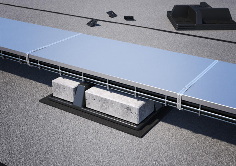
Wind loads: What you have to take into account during planning
Wind can pose a real challenge during installation. Here, you will learn how to reliably secure cable support systems against wind loads.
IEC 61537:2006 – requirements for cable support systems
What requirements do cable support systems have to meet? Product standard IEC 61537:2006 sets out clear standards for load capacity, safety and labelling.
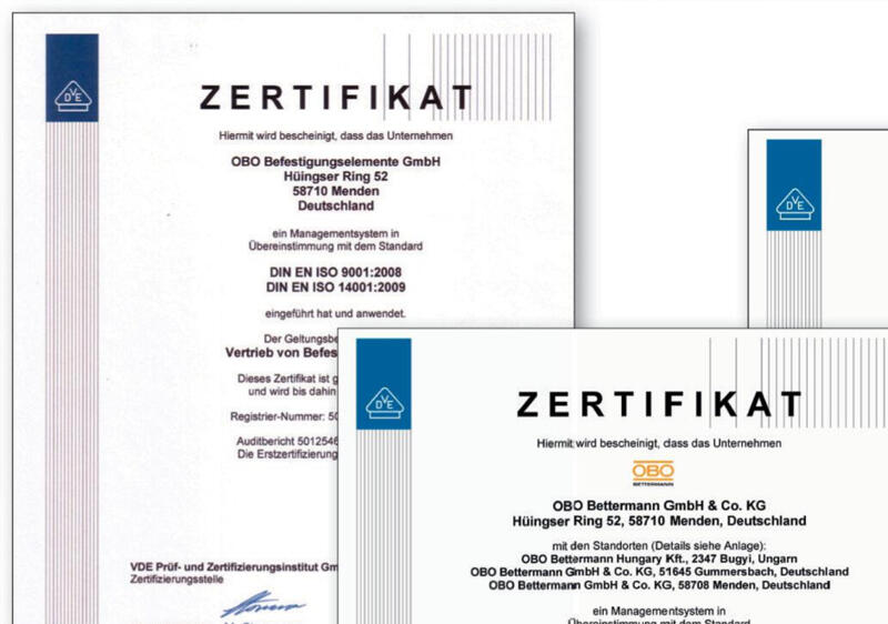
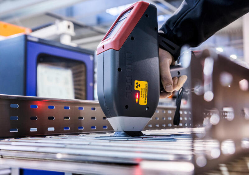
Tested quality – certificates, standards and test marks at a glance
From ISO to UL: Learn which certificates and test marks attest to the quality and safety of our cable tray systems, nationally and internationally.
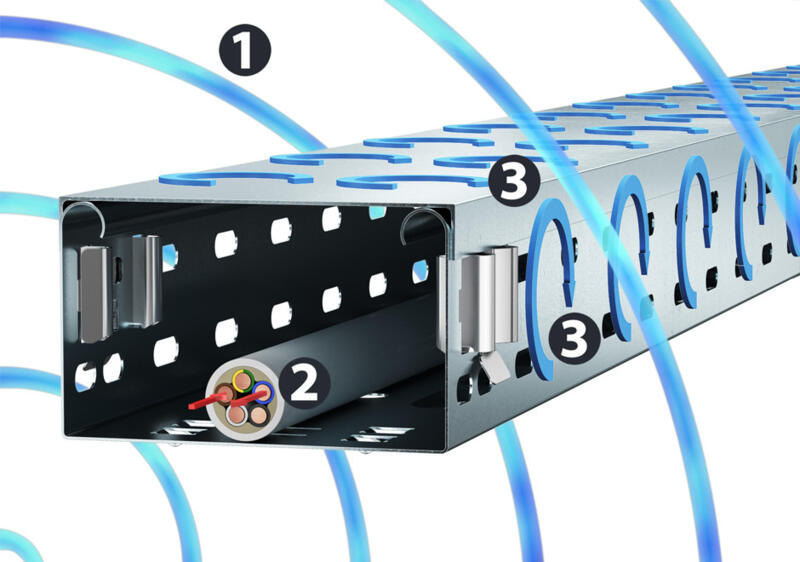
Protection against interference: EMC shield attenuation in cable support systems
Electromagnetic interference fields can cause entire systems to fail. Magnetic shield attenuation provided by properly installed cable routing systems offers protection.