Load values, product standard IEC 61537:2006
In Germany, DIN EN 61537:2007 09 “Cable management – Cable tray systems and cable ladder systems” is the currently valid translation of IEC 61537:2006. It specifies the requirements and testing for cable support systems, which are intended to support and house cables, as well as other electrical resources in electrical installations or communication systems.
FAQ – requirements according to the product standard
What general requirements apply for cable support systems and where are they laid out?
What test requirements apply to cable support systems?
How do cable support systems have to be labelled?
Which information should be available in the mounting instructions for cable support systems?
Which information on cable support lengths must the mounting instructions include?
Classification
All the cable support systems are classified using a numerical system in accordance with Chapter 6 of the product standard IEC 61537. This allows the user to detect easily which properties a cable support system offers.
| 6.1 | Material |
|---|---|
| 6.1.1 | Metallic component |
| 6.1.2 | Non-metallic component |
| 6.1.3 | Mixed construction |
| 6.2 | Resistance against the spread of flames |
|---|---|
| 6.2.1 | Flame-spreading |
| 6.2.2 | Not flame-spreading |
| 6.3 | Electrical conduction property |
|---|---|
| 6.3.1 | Without electrical conduction properties |
| 6.3.2 | With electrical conduction properties |
| 6.4 | Electrical conductivity |
|---|---|
| 6.4.1 | Electrically conductive system component |
| 6.4.2 | Electrically non-conductive system component |
| 6.5 | Corrosion/surfaces |
|---|---|
| 6.5.1 | Non-metallic system components |
| 6.5.2 | Steel with metallic surface treatment or rustproof steel |
Classes 0–9D
| Class | Reference material and surface treatment |
|---|---|
| 0a | None |
| 1 | Galvanic zinc coating with a minimum thickness layer of 5 m |
| 2 | Galvanic zinc coating with a minimum thickness layer of 12 m |
| 3 | Hot-dip galvanised (strip galvanised) to Level 275 according to EN 10327 and EN 10326 |
| 4 | Hot-dip galvanised (strip galvanised) to Level 350 according to EN 10327 and EN 10326 |
| 5 | Hot-galvanised (piece galvanised) with a minimum layer thickness of 45 µm according to ISO 1461 |
| 6 | Hot-galvanised (piece galvanised) with a minimum layer thickness of 55 µm according to ISO 1461 |
| 7 | Hot-galvanised (piece galvanised) with a minimum layer thickness of 70 µm according to ISO 1461 |
| 8 | Hot galvanised (piece galvanised) with a minimum layer thickness of 85 µm according to ISO 1461 (normally high-alloy silicon steel) |
| 9A | Stainless steel, manufactured according to ASTM: A 240/A 240M – 95a Designation S30400 or EN 10088 degree 1-4301 without finishingb |
| 9B | Stainless steel, manufactured according to ASTM: A 240/A 240M – 95a Designation S30400 or EN 10088 degree 1-4404 without finishingb |
| 9C | Stainless steel, manufactured according to ASTM: A 240/A 240M – 95a Designation S30400 or EN 10088 degree 1-4301 without finishingb |
| 9D | Stainless steel, manufactured according to ASTM: A 240/A 240M – 95a Designation S30400 or EN 10088 degree 1-4404 without finishingb |
a For materials, which do not have a declared corrosion resistance classification. b The end treatment process is used to improve the protection against gap corrosion and the contamination of other steels. | |
| 6.5 | Corrosion/surfaces |
|---|---|
| 6.5.3 | Aluminium alloy or other metals |
| 6.5.4 | With metallic and organic coating |
| 6.6 | Temperatures |
|---|---|
| 6.6.1 | Minimum temperature –50 °C / –40 °C / –20 °C / –15 °C / –5 °C / +5 °C |
| 6.6.2 | Maximum temperature +150 °C / +120 °C / +105 °C / +90 °C / +60 °C / +40 °C |
| 6.7 | Perforation of the base area of the cable tray length |
|---|---|
| A | ≤ 2 % |
| B | > 2 % |
| C | > 15 % |
| D | > 30% (IEC 60364 5 52) |
| 6.8 | Perforation of the base area of the cable tray length |
|---|---|
| X | ≤ 80 % |
| Y | > 80 % |
| Z | > 90% (IEC 60364 5 52) |
| 6.9 | Impact resistance |
|---|---|
| 6.9.1 | Up to 2 J |
| 6.9.2 | Up to 5 J |
| 6.9.3 | Up to 10 J |
| 6.9.4 | Up to 20 J |
| 6.9.5 | Up to 50 J |
Mechanical load testing to determine the safe working load (SWL)
An important core task of the standard is to verify the data produced on the safe working load in a comparable and reproducible framework. This is achieved using various test methods. Of importance for the practical application is that the connectors are to be arranged in the manner described in the instructions or data sheets of the manufacturer, as otherwise the safe working load cannot be guaranteed.
Generally, two tests must be carried out – the minimum temperature test and the maximum temperature test. With steel components, it is sufficient to test at a temperature in the range between –20 °C and +120 °C, as the mechanical properties, according to the standard, do not deviate by more than 5% of the mean value of the property values on account of the temperature change.
All the testing methods intend for a pre-load of 10% is applied to cable support lengths and 50% for support elements, in order to allow settling. Then, the load is removed again and the deformations measured from this state.
All the samples on test are firstly subjected to the nominal safe working load (SWL) and, if the failure criteria are passed, then the load is increased to 1.7x the safe working load.
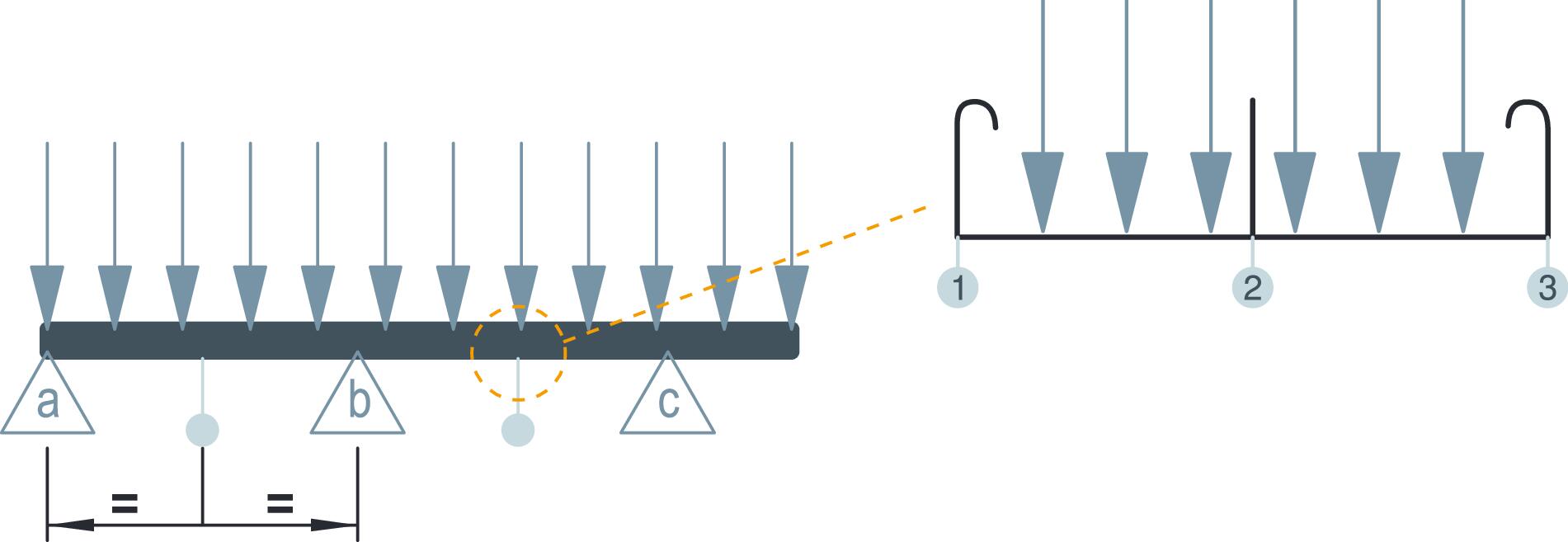
The first failure criterion is the approved deformation under the nominal safe working load. Here, the lateral bending of the cable support lengths and the fittings may not be greater than a maximum of 1/100 of the support spacing and the transverse bending not greater than a maximum of 1/20 of the nominal width (cable support lengths, fittings, support elements). In addition, for brackets, the transverse deformation is limited to a maximum of 30 mm under the SWL. Under the SWL, a support may bend by a maximum of 1/20 of its length. Of course, the items on test and connections may not show any visible damage or breakages.
The lateral bending is measured in the middle of each field [ab] and [bc] as a calculated mean value of the left and right outer side (1 and 3) of a cable support. The transverse bending is determined at the same location as the difference between the mean value of the sense in the middle (2) of the cable support base and the mean value of the lateral bending (ø13).
The second failure criterion is that the system may not collapse under an increased 1.7x load. However, strong deformation and bending are permitted under the increased load.
Special loads, such as the so-called human load, snow, rain, ice, wind, seismic activity or thermal tensions, are not tested with this method. According to the standard, snow, the wind load and other environmental risks are not considered to be the responsibility of the manufacturer. If necessary, the planner of the installation should take these influences into account.
This method basically checks the safe working load (SWL) of the cable support lengths and their connections, fittings and support elements.
The tests for multi-field supports, mounted on the vertical plane with a horizontal direction of movement (typical application in power stations) and for rising sections, mounted in the vertical plane with a vertical direction of movement, are still being discussed in the currently valid version of the standard. The new draft standard plans a standardised test for this. OBO Bettermann can already present some load values according to this standard for the power station application.
For completeness, the so-called impact resistance according to IEC 60068-2-75 should be discussed at this point. Here, a hammer with a defined mass is struck against various items on test from a specified height, firstly on the base area or rung, and then dropped on each side section. After the test, the items on test may not show any signs of destruction or deformations which impede safety.
| Impact energy [J] | Hammer mass [Kg] | Fall height [mm] |
|---|---|---|
| 2 | 0.5 | 400 |
| 5 | 1.7 | 295 |
| 10 | 5.0 | 200 |
| 20 | 5.0 | 400 |
| 50 | 10.0 | 500 |
Cable support lengths as multi-field support
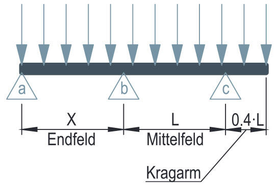
A multi-field support is considered to be a sequence of cable support elements (trays or ladders) and support elements erected for more than one field between the support points, i.e. it has multiple support points. This is the most common installation type of cable support systems.
Most cable support systems are mounted with their base in the horizontal plane and usually also run in a horizontal direction. For this installation type, the standard offers five different types of test, which are linked to certain conditions. This should ensure safe operation under all conditions.
| Test type | Conditions |
|---|---|
| I |
|
| II |
|
| III |
|
| IV |
|
| V |
|
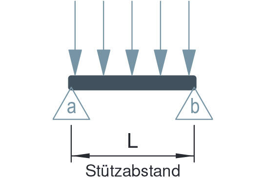
Cable support lengths as single-field support
If a cable support system section consists of cable support lengths and exactly two support points arranged at each end of the section, then this is termed a single-field support. In other words, it has a single support spacing. This may be the case when crossing corridors or, in hall construction, when crossing from one support pillar to another, if the cable support system does not continue across multiple field, i.e. the system ends at each support. This distinction from the multi-field support is important as the load on the system changes every metre at the same cable load.
Single-field supports in the horizontal plane are primarily mounted with a horizontal direction of movement. During the test, the connector must be located in the centre of the field, if not otherwise restricted by the manufacturer.
Fittings
For fittings (bend, T piece, cross-over), mounted with the base in the horizontal plane with a horizontal system direction of movement, the standard also prescribes a test if the fitting itself is not supported by a mounting element. The distance Y to the next support is stated by the manufacturer.
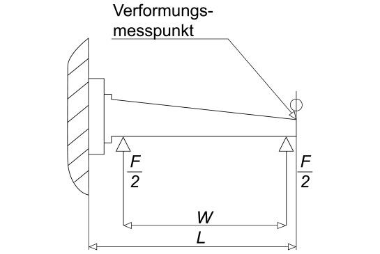
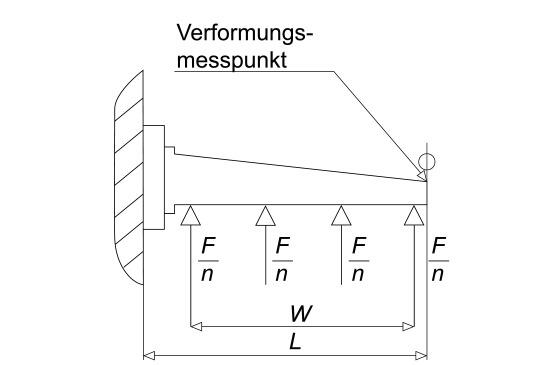
Bracket
Brackets are tested for use on the wall or support (graphic 1). The load is applied at two points, if the bracket is designed for cable trays and cable ladders (graphic 2). If the bracket is only constructed for cable trays, then the load is applied evenly at multiple locations (graphic 3). This reduces the stress on the bracket, allowing increased safe working loads. At OBO Bettermann, we generally test the worse case to ensure that the safe working load is always achieved.
The figures show the standardised test set-up.
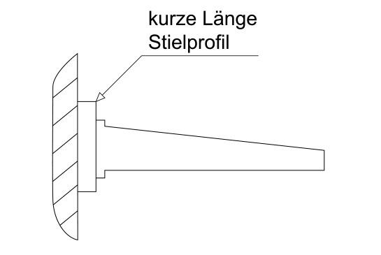
Supports
The so-called suspended supports are subjected to no less than three tests.
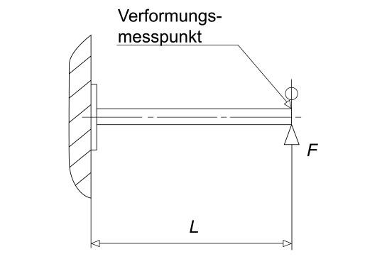
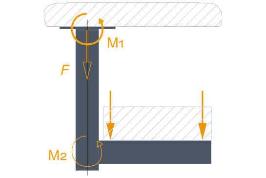
Testing of the bend torque of supports on ceiling plates (graphic 1), ideally with 0.8 m support length. The safe working load is stated as M1 in Nm or kNm.
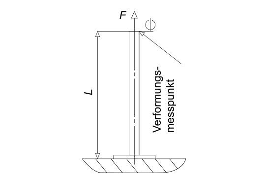
Testing of the tensile strength of supports or the head plate (graphic 2) as SWL data as F in N or kN.
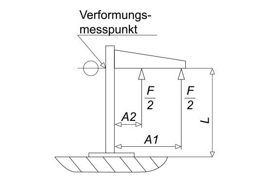
Testing of the bend torque of supports with brackets (graphic 3), given as M2 in Nm or kNm. This test must be carried out on lengths L = 0.5 m, 1.0 m and 1.5 m, assuming that the items are available in the product range. Here, the supports are tested in combination with the mounted strongest and largest bracket recommended for the support.
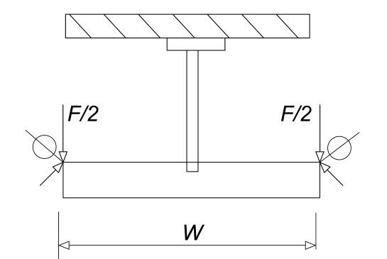
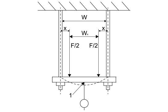
A smaller role is played by the tests for a central (symmetrically) fastened bracket (graphic 4) and for supports with brackets/ceiling suspension (graphic 5) fastened at the ends. The latter is given the colloquial name of a monkey swing. Here, two threaded rods are used as elements being pulled or suspended supports with a horizontal stiff profile as a tray base.
Safe installation of supports with brackets
The installation of a suspended support with bracket is considered as safe when the following conditions are fulfilled.
- The load applied to each bracket is less than the safe working load specified for the individual bracket (10.8.1).
- The bending torque of supports with brackets M2 is less than the safe working load for the support lengths used (10.8.2.3). An interpolation between the test results of various lengths is permitted.
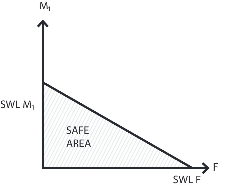
- The result bending torque on the ceiling plate M1 and the resulting force F are in the safe area.
Electrical tests
In normal use, the products of the standard are passive with regard to electromagnetic influences (transmission and immunity). If cable support systems are installed as part of a cabling installation, then the installation can transmit electromagnetic signals or be influenced by them. The level of influence is dependent on the nature of the installation in its operating environment and on the devices connected to the cabling.
According to IEC 61537, the electrical conduction properties or the electrical insulation properties are tested. This is dependent upon how the system was classified.
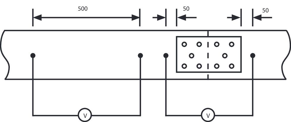
Cable support systems, classified according to 6.3.2 as “with electrical conduction properties, must have a sufficient electrical conductivity, in order to ensure the equipotential bonding and connection(s) with the earth, if this is required according to the application of the cable support system. Here, the system, consisting of two cable support lengths and the system-dependent connector, is subjected to an alternating current of 25 A at an idle voltage of less than or equal to 12 V (AC 50–60 Hz). A first voltage drop is measured over a section of 50 mm on each side of the connector. The resulting impedance (transition resistance) may not exceed 50 mΩ. Various connectors must (if available) be tested separately. A second voltage drop is measured over a section of 500 mm without a connection point. The resulting impedance may not exceed 5 mΩ/m.
Cable support systems, classified according to 6.4.2 as an “electrically non-conductive system component”, shall be considered as non-conductive if the specific surface resistance is greater than 100 mΩ. Metallic cable support systems with a coating are always considered as being conductive.
Fire risks
A cable support system cannot generally represent the cause of a fire, only contribute to it. Regarding the design of cable support systems, the standard prescribes that non-metallic mixed materials, which may be subjected to exceptional heat due to electrical errors, must be non-flammable. For this, the glow wire test according to IEC 60695-2-11:2000 Section 4-10 is carried out with a glow wire temperature of 650 °C. System components which do not spread flames may either not ignite or have a limited spread of flames.
Additional contents
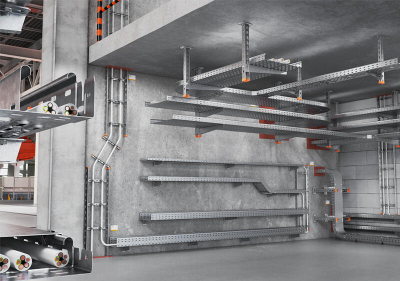
Cable support systems at a glance
Robust, safe, long-lasting – learn more about cable support systems, corrosion, surfaces and materials.
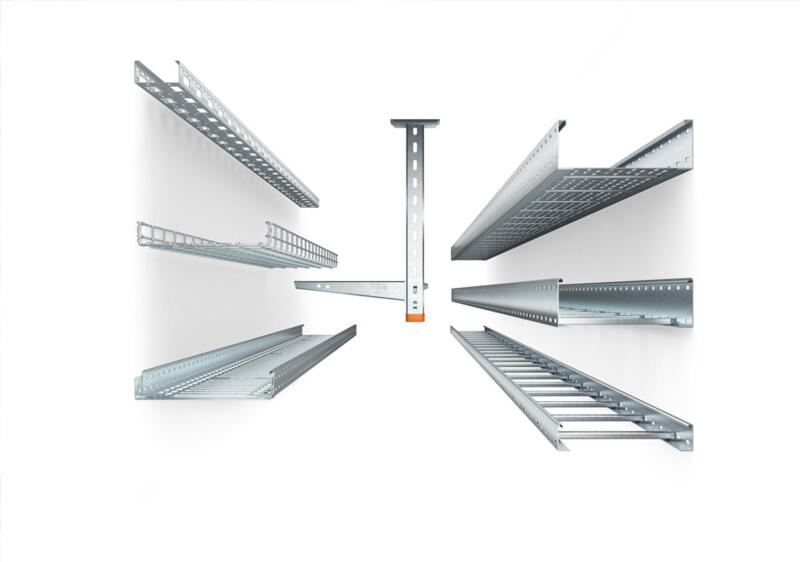
Finding the right cable support system
How do you choose the right cable support system for a planned installation? We will advise you on why cable volume and cable load are some of the important criteria.
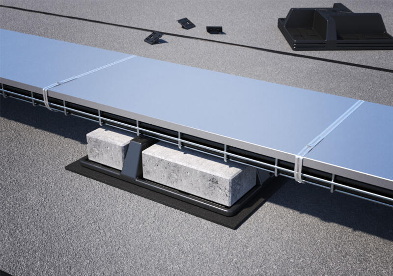
Wind loads: What you have to take into account during planning
Wind can pose a real challenge during installation. Here, you will learn how to reliably secure cable support systems against wind loads.
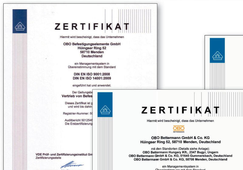
Tested quality – certificates, standards and test marks at a glance
From ISO to UL: Learn which certificates and test marks attest to the quality and safety of our cable tray systems, nationally and internationally.
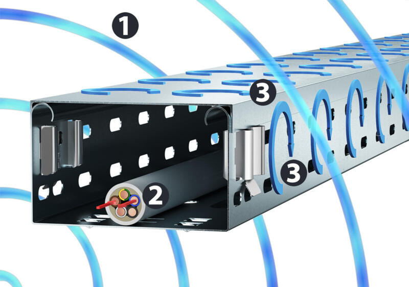
Protection against interference: EMC shield attenuation in cable support systems
Electromagnetic interference fields can cause entire systems to fail. Magnetic shield attenuation provided by properly installed cable routing systems offers protection.