Declarations
Certifications and test marks as an expression of high product quality
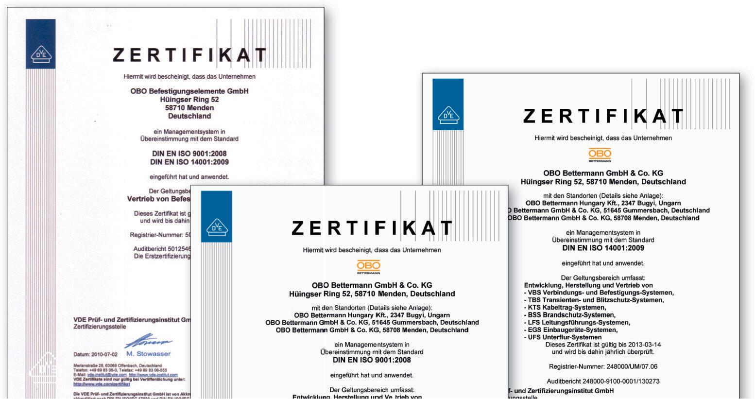
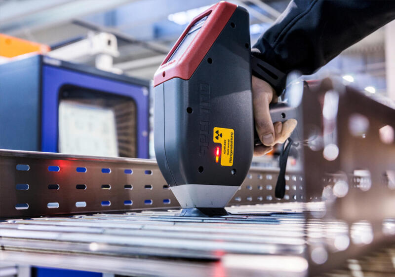
For OBO, product quality is closely connected to continuous testing and checking − which is why we manufacture almost all our products ourselves. This enormous depth of production is an expression of our demand for quality. From construction and the raw materials used, through production, and on to logistics, our employees vouch personally for the quality and availability of the OBO products. The multitude of approvals emphasise our high demand for quality and product functionality. Besides our integrated quality management, which forms the basis of our ISO 9001 certification dating back to 1994 and stands for clear, lived processes, we also possess further product-specific certificates, depending on the item and the area of requirements. These guarantee that the appropriate products correspond to the national standards and are issued by independent certification institutes. In addition, there are annual audits, depending on the certificate and institute, in order to test the current manufacturing processes.
VDE symbol approval
VDE is the Association for Electrical, Electronic and Information Technologies, their study and the technologies and applications based upon them. The VDE mark on electrical equipment is proof that the equipment complies with VDE regulations and/or European or international harmonised standards, and meets the safety requirements of the applicable directives. The VDE symbol standard for the safety of the product with regard to electrical, mechanical, thermal, toxic, radiological and other risks. The VDE test mark guarantees, for example, that our RKSM cable tray has been tested correctly according to the basic standards.
North American test marks for cable support systems
Many OBO products are certified for use in the US and Canada. The North American markets require concrete proof of product safety and compliance with standards, in particular for construction projects, industrial applications and public invitations to tender.
The following test marks from the Underwriters Laboratories (UL) and the Canadian Standards Association (CSA) are crucial for product selection and approval.
UL Listed
The UL Listed mark certifies that a complete end product, such as a cable tray, housing or distributor, has been tested by UL and approved in accordance with the applicable US safety standards. The test is performed under real operating conditions and includes electrical safety, material properties and fire protection, among other things.
Target market: USA
Typical application: For direct use in the field, often required in industrial projects or public buildings.
cUL Listed
The Canadian equivalent to the UL Listed mark. The entire product is also tested here – but in accordance with the requirements of the Canadian Electrical Code (CEC)/CSA standards. The lowercase “c” on the left of the logo indicates the Canadian approval.
Target market: Canada
Particularity: A separate test mark is required for Canada, even with UL certification.
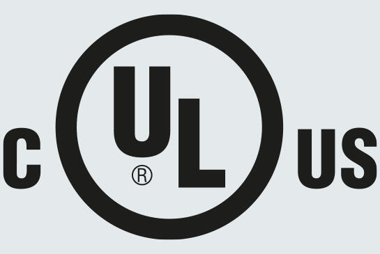
cULus Listed
This mark combines the approvals for the USA and Canada. It indicates that a product can be used in compliance with standards in both countries, doing away with the need for dual certification.
Target market: USA & Canada
Recommendation: Ideal solution for international projects or series products exported to North America.
UL Recognized Component
This test mark is intended for individual components that will be integrated into a complete system later, such as terminal strips, plug connectors or internal switchgear cabinet elements. The test is application-specific and is focussed on reliable function in the final product.
Target group: OEMs, appliance manufacturers, switchgear cabinet construction
Note: Not a replacement for UL Listed if the end product has to be certified.
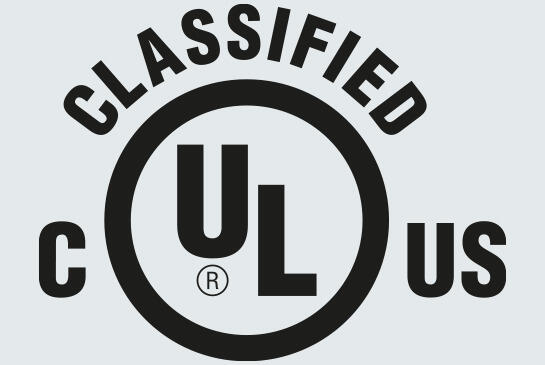
UL Classified
This is a targeted evaluation of specific properties, e.g. fire resistance (UL94), IP classification or EMC behaviour. Especially relevant for components with defined protective function, e.g. fire protection cable trays or housing in rough environments.
Target market: USA (in some cases also internationally)
Technical basis: Combination of UL test procedure and standard series like NEMA, ANSI, etc.
CSA test mark
CSA-us
This test mark is issued by the CSA Group for products that were tested in accordance with American regulations. From a technical perspective, it is largely equivalent to UL, but is issued by a different certification body.
Target market: USA
Relevance: Often accepted as an equivalent alternative to UL – for example for local authority approvals (AHJ).
CSA
Denotes products that are tested and approved fully in accordance with Canadian standards (e.g. C22.2). In Canada, CSA is established as an officially recognised test authority.
Target market: Canada
Typical in: Installations requiring proof according to Canadian Electrical Code (CEC).
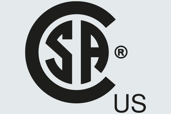
CSA-us/c
Combined test mark for both markets. The CSA Group tests according to US and Canadian standards and confirms unrestricted usability in both countries.
Target market: USA & Canada
Practical benefit: Reduces testing effort and simplifies listings in invitations to tender and proof of compliance with standards.
EPD Environmental Product Declaration
The requirements for sustainable production processes and the demand for environmental declarations by architects and planners continue to increase, as they frequently serve as the decision-making basis for the optimum combination of construction products.
An environmental product declaration differs from certificates such as the UL certification, because, here, the data of the company and the products is not evaluation, but simply summarised according to the standards described below. The basis for an EPD is the international standards ISO 14025 and EN 15804, which, on the one hand, regulate the basic principles and methods for the type III environmental labelling and, on the other, define the appropriate product category, according to the construction product. Eco-balances are used to compile EPDs and are created according to DIN EN ISO 14040 and 14044.
EPDs not only allow the life-cycle assessment and evaluation of buildings, but also the integral planning. Even in the drafting phase, architects and technical planners use EPDs to compare various components, construction methods and variants and can thus select the ideal combination of construction products for each individual building.
Thanks to EPDs for materials, construction products and components, it is now possible to include ecological aspects in the sustainability evaluation of structures. The emphasis is primarily on the basic information for the evaluation of ecological building quality. The comprehensive and detailed eco-balance data and information contained in the EPDs are summarised in a standardised format over just a few pages.
Here, the phases of manufacture and disposal are taken into account in a life-cycle analysis. In addition, our EPDs are published by Deutsche Gesellschaft für Nachhaltiges Bauen (DGNB) and, in this context, carry the DGNB label. This means that the internationally recognised EPDs form a key cornerstone of the building certification systems of DGNB, BNB, BREEAM and LEED.
Maintenance of electrical function for safety-relevant electrical systems
If there is a fire, key technical equipment, such as emergency lighting, fire alarm systems or smoke extraction systems, must continue to function. In addition, certain technical systems must support the fire brigades in fighting fires for a sufficiently long period of time. To guarantee the power support and thus the maintenance of electrical function for these electrical systems during a fire, the appropriate installations must be created with special cables and routing systems.
Technical equipment that maintains the electrical functionality is required for the following buildings and areas: hospitals, hotels, restaurants, tower blocks, meeting places, shops, closed indoor car parks, metro systems, the chemical industry, power stations and tunnels. These buildings are frequently visited by large numbers of people, creating an increased safety risk for gatherings of people. However, with certain systems, property and the environment must also be protected.
The requirement for electrical installations that maintain the electrical functionality is a component part of the construction regulations. Here, the maintenance of electrical function relates solely to the areas connected to the power supply of safety-relevant electrical systems. Besides the items listed above, these also include, for example, alarm systems or automatic extinguishing systems. Here, the regulations require that the power supply must be guaranteed for a specific period of time, even if there is a fire.
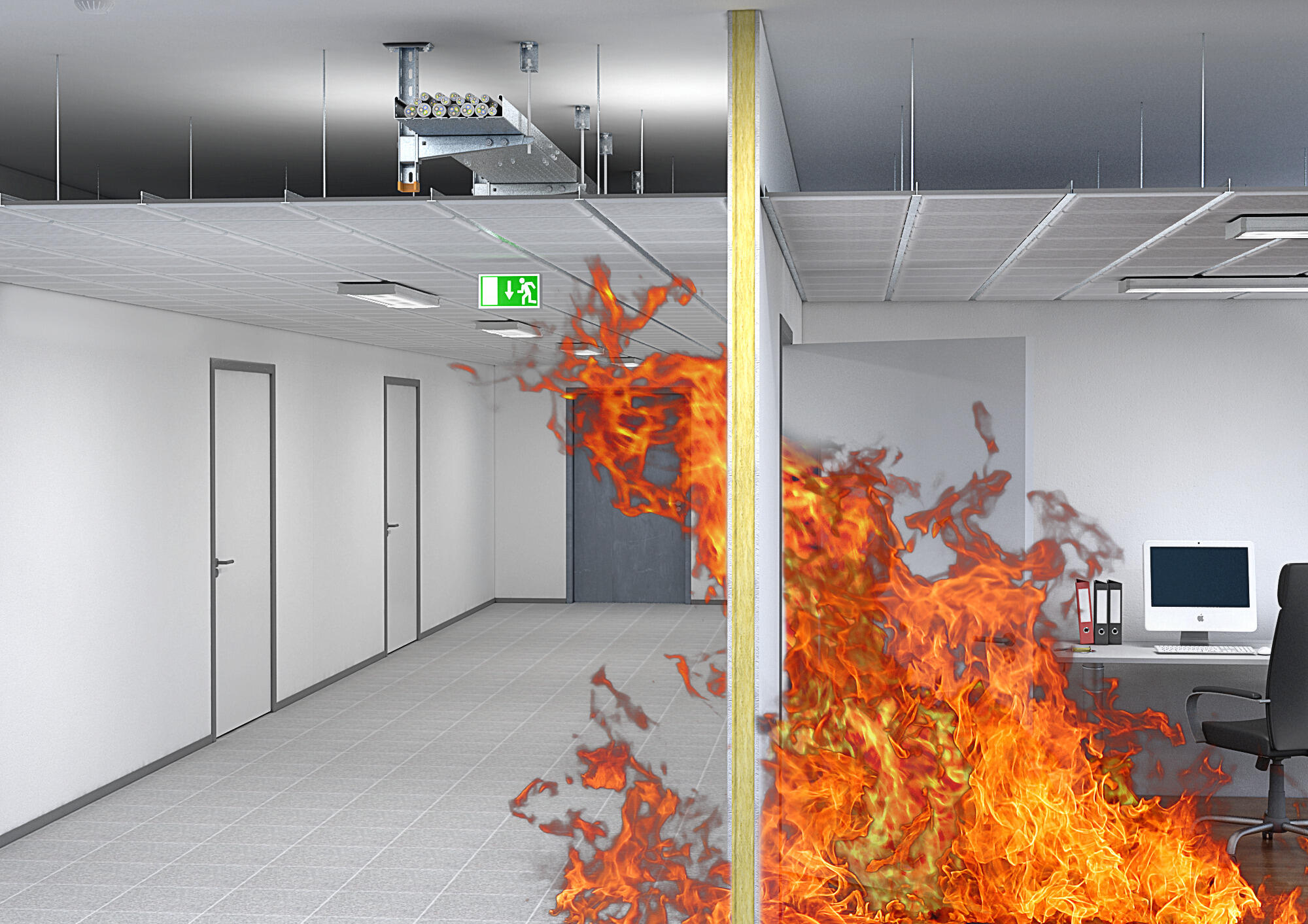
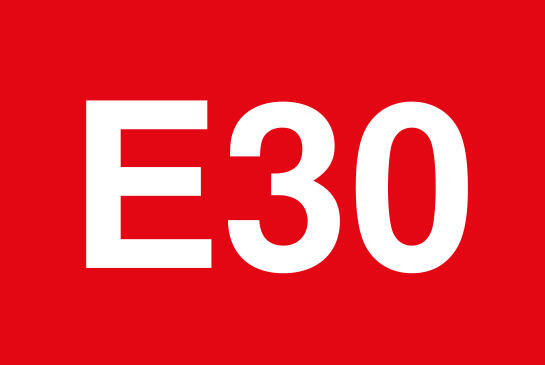
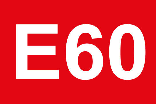
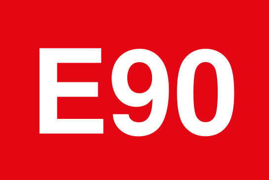
Cable systems with integrated maintenance of electrical function
A cable system with integrated maintenance of electrical function according to DIN 4102 Part 12 is considered as the routing system (cable ladders, cable tray, clips, etc.) in combination with cables. The proof of the maintenance of electrical function must be provided by a fire test at an independent material testing institute. Depending on the function length passed, the cable system receives the classifications E30, E60 or E90. This is documented in a testing certificate.
There is currently no European standard on the maintenance of electrical functionality, but there are some national test regulations, e.g. according to PAVUS in the Czech Republic. The most widely spread and accepted is testing according to DIN 4102 Part 12. Work is currently being carried out on the European standards.
Certified fire protection: safe solutions for safe buildings
Whether proofs of application or test and classification standards – we help you stay on top of things.
DIN 4102 Part 12: Contents and requirements
DIN 4102 Part 12 defines standard routing systems with appropriate mounting parameters. In addition, there are so-called cable-specific routing types, which allow more economic applications, e.g. by increasing the fastening distances or higher approved cable loads. The tests according to DIN 4102 Part 12 are supplementary tests, in addition to the requirements from the standards of the electrical and mechanical applications. You will find more information in the Fire protection guide .
VDE 0100 Earthing: Definition, legal and standard requirements
For their approval, cable support systems must correspond to the standard DIN EN 61537 “Cable management – Cable tray systems and cable ladder systems”. A component part of DIN EN 61537 is also the proof of continuous electrical conductivity, required by Point 11 – Electrical properties.
Whether or not a support system must be included in the equipotential bonding is specified at another point. According to the generally valid requirements in DIN VDE 0100, a cable support system need not be included in the equipotential bonding, as cables are usually routed there which, besides their jacketing, also possess wire insulation. As, according to the VDE, there are no double errors, the standard considers that the double insulation excludes the possibility of the support system being energised is there is an error.
However, if the support system is defined as a foreign conductive part in the hand area according to DIN VDE 0100 Part 410, then it must be included in the equipotential bonding. Metallic cable routing ducts or trunking or device installation ducts or trunking or rising sections would be typical examples of this.
If cabling for information technology is routed on or in the cable support systems, then the support systems must always be included in the equipotential bonding.
Then, DIN EN 50174-2 “Information technology - Cabling installation – Part 2: Installation planning and practices inside buildings” applies. Accordingly, the support system must be included in the equipotential bonding according to Point 5.3.3.2 “Electrically conductive cable routing systems” and 5.3.3.3 “Electromagnetic shielding”.
To be on the safe side, and in case of error, to guarantee safe switch-off of the error currents, OBO always recommends including support systems for cable routing in the equipotential bonding.
International standardisation
International standardisation in the field of electrical engineering is brought together by the IEC (International Electrotechnical Commission) as the organisation for the introduction of international standards. A total of 173 countries are represented in this commission, which are working to unify standards.
In turn, these countries possess national committees and commissions to represent their national interests. As an example, for Germany, DKE (Deutsche Kommission Elektrotechnik) is the responsible organisation for the compilation of standards. This organisation is a member in the IEC and the CENELEC (European Committee for Electrotechnical Standardisation).
Each member state possesses a national commission and sends experts into the different committees for the creation of the international standards.
However, these national commissions can specify deviations for the valid national standard, on the basis of the international standard. This means that there may be requirements that deviate from an IEC standard.
For this, there are certain rules that the national committee must comply with. An important aspect is that the deviations may only represent a tightening of the currently valid IEC standard. A softening or reduction of the requirements is not permitted.

Structure of the standard organisations
International standards are not developed in isolation, but instead in collaboration between different organisations at an international, regional and national level. This structure ensures that technical standards are comparable globally, but can also be adapted to national circumstances.
While organisations such as IEC, ISO or ITU develop global standards, committees such as CENELEC or ETSI ensure harmonisation in Europe. National committees such as DKE or DIN ultimately assume responsibility for implementation and represent the interests of their country.
For planners, heads of construction and installers, an overview of this structure is helpful to correctly classify standards, recognise responsibilities and realise projects in compliance with regulations.
International level
ISO – International Organization for Standardization
Global organisation for general technical, organisational and systematic standards. Examples: ISO 9001 (quality management), ISO 14001 (environment management).
→ Area of application: across industries, valid worldwide
IEC – International Electrotechnical Commission
Responsible for international standards in electrical engineering. Lays down electrical safety, protection classes, system construction, testing procedures and more.
→ Typical standard: IEC 61439 for low-voltage switchgear assemblies
ITU – International Telecommunication Union
United Nations organisation for global standards in telecommunications. Coordinates, for example, frequency spectrums, 5G standards, Internet protocols.
→ Relevance: In all projects with network technology, data transmission or mobile communications

European level
CEN – Comité Européen de Normalisation
Responsible for development and harmonisation of European standards in non-electrotechnical areas, such as construction products, machines, services.
→ Basis for CE marking of many products
CENELEC – Comité Européen de Normalisation Électrotechnique
European equivalent to the IEC at a regional level. Develops standards for the inner-European market, e.g. for cables, protection systems, EMC.
→ Relevance: Basis of many DIN EN standards in the electrical industry
ETSI – European Telecommunications Standards Institute
Develops European standards for telecommunication, radio, Internet and connected systems (e.g. IoT, 5G, smart grid).
→ Relevance: Anywhere data transmission technologies are installed
German level
DIN – Deutsches Institut für Normung e. V.
Central national standards organisation in Germany. Reflects European and international standards (e.g. as DIN EN or DIN ISO) and develops its own standards.
→ Significance: Often integrated directly into technical rules or statutory regulations
DKE – Deutsche Kommission Elektrotechnik in DIN und VDE
Responsible for electrotechnical standards in Germany. Represents German interests in IEC and CENELEC, issues, e.g. VDE standards.
→ Important: e.g. for installation standards in accordance with DIN VDE 0100 or product standards
EC declarations of conformity
The declaration of conformity is a written confirmation of a conformity evaluation. With it, the responsible party declares and confirms that a product, service or organisation possesses the properties specified in the declaration.
There are no restrictions to the object of a declaration of conformity. This means that it is possible to declare the conformity of products, processes, people, jobs or management systems.
The CE mark is the result of an EC declaration of conformity and a conformity mark, which states that a product agrees with the harmonisation regulations of the European Union. It is the visible consequence of the overall process of conformity evaluation and the resulting declaration of conformity.
The CE label is thus an “image symbol” and does not represent an abbreviation.
The CE symbol is always applied by the manufacturer and is done in clearly visible, legible and permanent location on the product or the product type plate. If this is not possible, it can also be attached to the packaging or the accompanying documents.
To compile a declaration of conformity and the resulting CE labelling, some things must be observed which must always be complied with. The “responsible manufacturer” or their representative, located in the EU, provides confirmation, at their own responsibility, of the legality.
- A declaration of conformity can only be compiled with a directive of the European Parliament and Council.
- The harmonisation of the legal requirements of the member states for free market access is described in the directives.
- The basis of the conformity evaluation, as well as the compilation of the declaration, is the harmonised standards assigned to the appropriate directive.
- Products and other services to be assigned to a standard and which are not harmonised with a directive may not be certified with conformity. These products must be certified with a manufacturer’s declaration, stating the applicable standard.
The required contents of the EU declaration of conformity is specified in the individual EU directives. By contrast, no requirements for the form and appearance are stated. General requirements for the contents of the declarations of conformity and also design suggestions are contained in the standards EN ISO 17050-1 and EN ISO/IEC 17050-2, as well as in the Blue Guide of the European Commission.
Additional contents
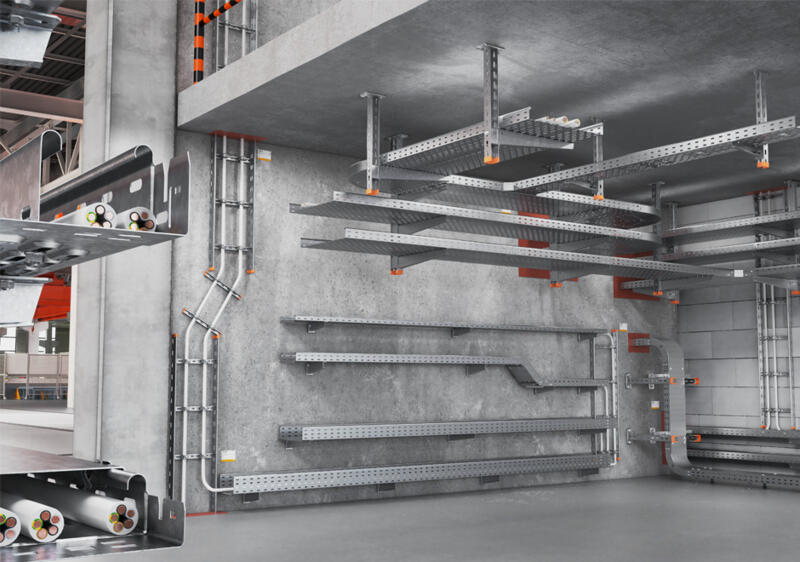
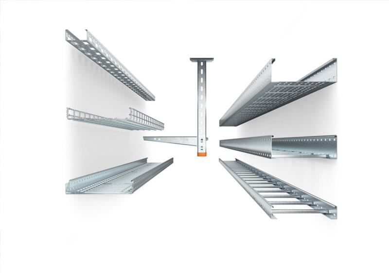
Cable support systems at a glance
Robust, safe, long-lasting – learn more about cable support systems, corrosion, surfaces and materials.
Finding the right cable support system
How do you choose the right cable support system for a planned installation? We will advise you on why cable volume and cable load are some of the important criteria.
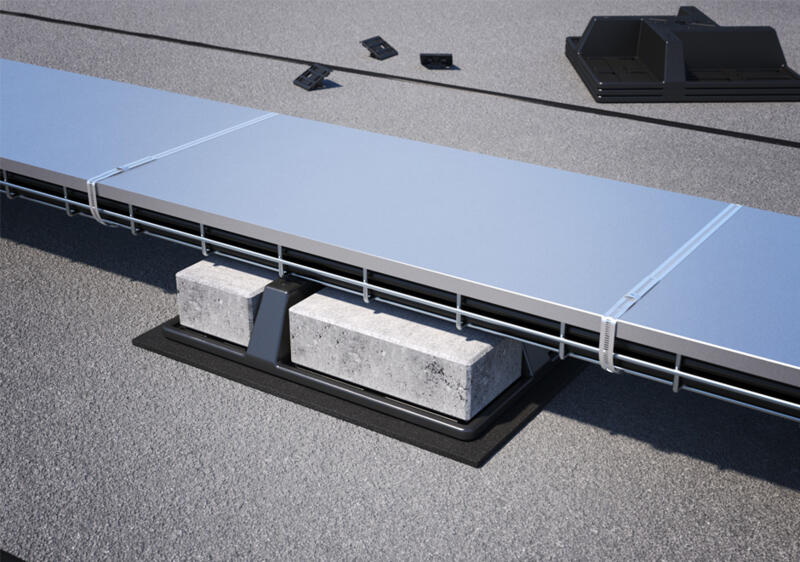
Wind loads: What you have to take into account during planning
Wind can pose a real challenge during installation. Here, you will learn how to reliably secure cable support systems against wind loads.
IEC 61537:2006 – requirements for cable support systems
What requirements do cable support systems have to meet? Product standard IEC 61537:2006 sets out clear standards for load capacity, safety and labelling.
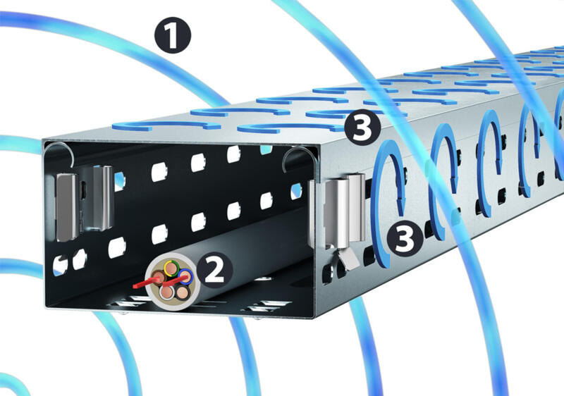
Protection against interference: EMC shield attenuation in cable support systems
Electromagnetic interference fields can cause entire systems to fail. Magnetic shield attenuation provided by properly installed cable routing systems offers protection.