EMC shield attenuation
Basic principles
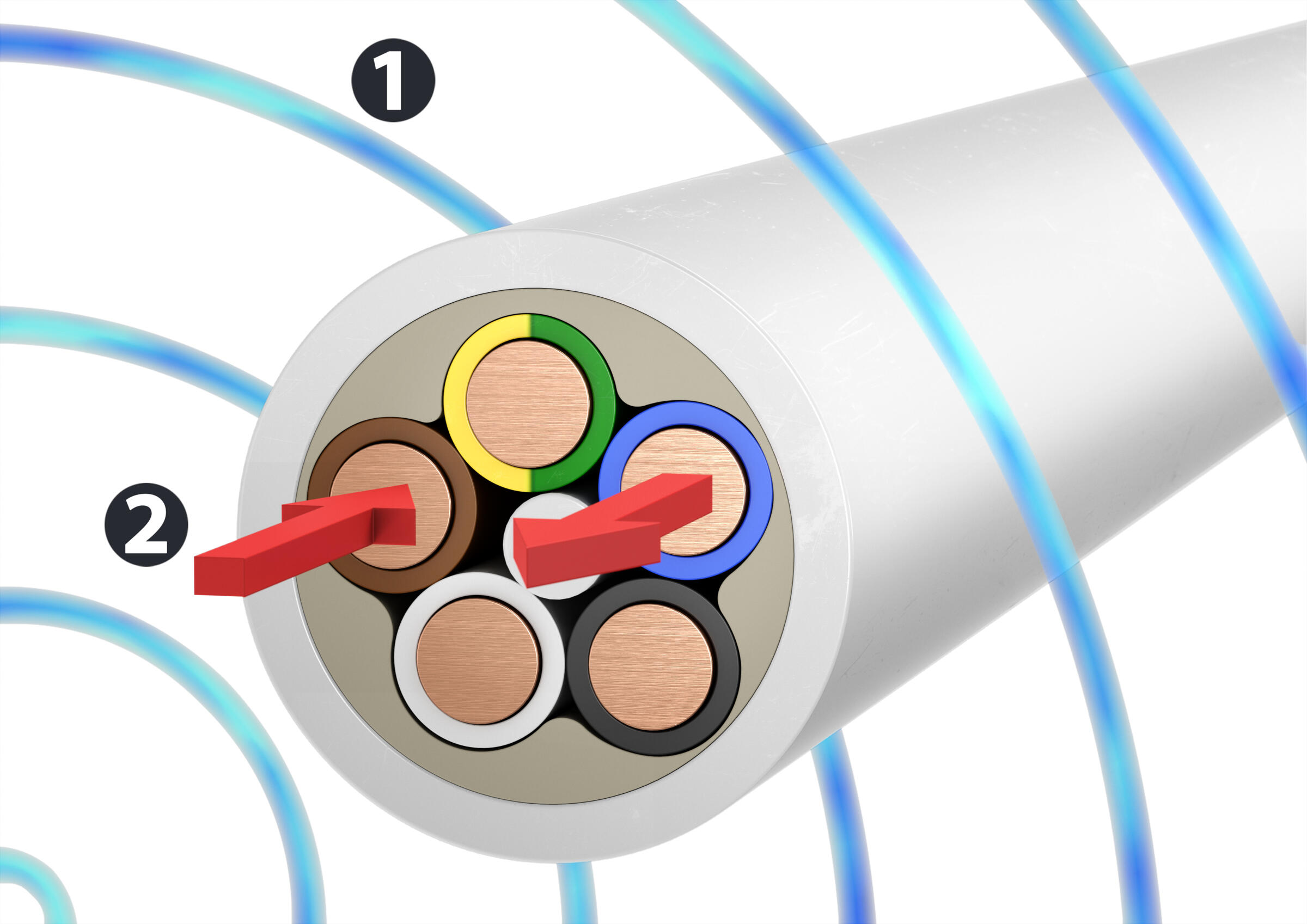
It may occur that cables have to be routed in areas with electromagnetic interference fields.
Sources of such electromagnetic interference fields can be, for example, electrical resources (motors) starting up, inverters, switching operations in electrical systems or lightning currents.
These interference fields can cause fault voltages and currents in cables, depending on their intensity, frequency and distance, which impede the function of the connected resources, or even destroy them.
With their high current values of over 200,000 amps and rapid rises of less than 0.25 µs (corresponding to a frequency of 1,000 kHz), lightning currents represent the strongest interference fields, which alternate rapidly.
The electromagnetic interference field generally consists of two different fields: the electrical field and the magnetic field. The different fields require different measures as protection against their damaging impact.
As protection against interference from the electrical field, a partition of conductive material is required, which is to be included in the equipotential bonding, and thus must be earthed. Depending on the frequency of the electrical interference field, mesh partitions are sufficient.
As protection against interference from the magnetic field, shielding, completely closed on all sides with conductive material, is required. In this shielding, an alternating magnetic field generates Foucault currents, which act against their cause (law of induction), thus creating an interference-free area within the shielding. Electrically non-conductive areas in the shielding, such as slits and openings, interrupt the Foucault currents, thus reducing the magnetic shield impact.
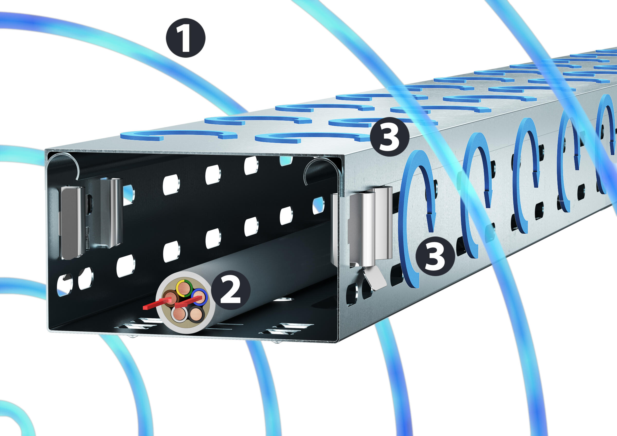
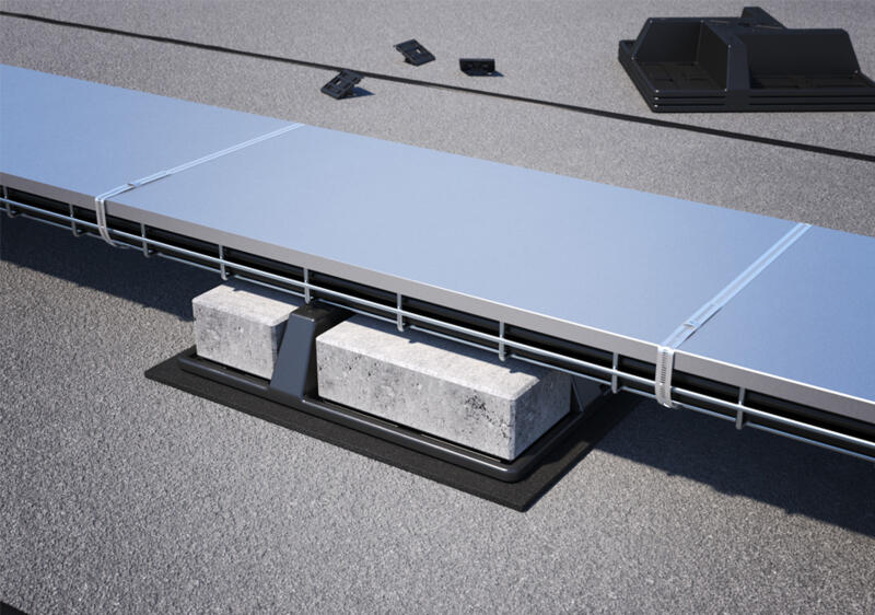
Closed, metallic cable support systems that are included in the equipotential bonding, such as cable trays, thus offer optimum protection of cables in areas with electromagnetic interference fields.
Our figure shows the interference field (1), the induced interference current (2) and Foucault currents (3).
Magnetic shield insulation
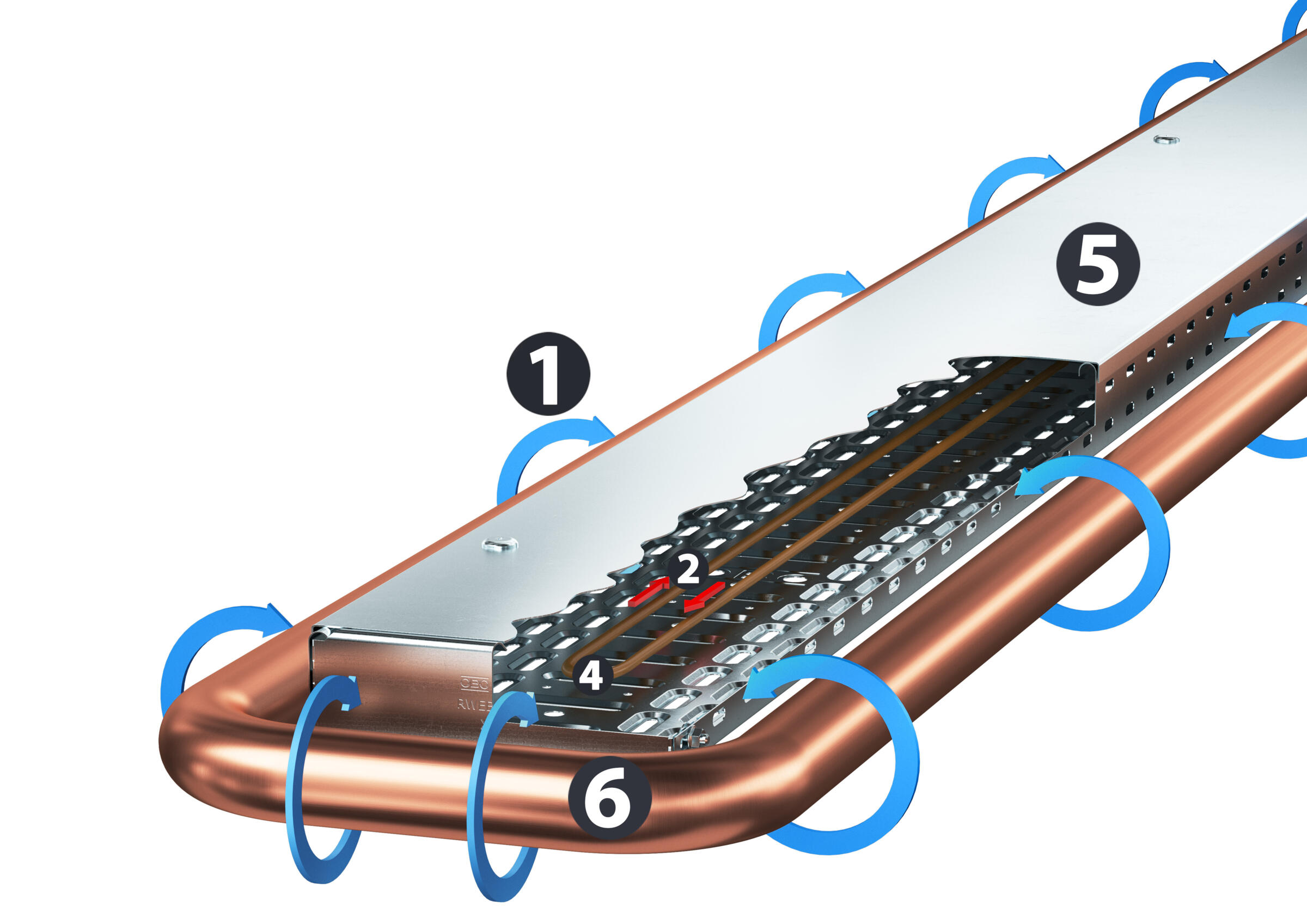
DIN CLC/TR 50659:2020-08 (VDE 0604-2-200) describes a testing procedure to measure the magnetic shield attenuation of cable support systems. A U-shaped antenna is used, through which a lightning current flows with a rise time of approx. 8 µs, creating a magnetic field of interference. In this arrangement, there is a closed conductor loop of two parallel cables in the centre.
The magnetic interference field generates an interference current in the conductor loop (induction law). The basic arrangement of the test structure is shown in the figure.
- Interference field
- Induced interference current
- Foucault currents
- Conductor loop
- Cable tray system
- U-shaped antenna
The magnetic shield attenuation (SE) is 20x the decadic logarithm from the ratio of the interference signal occurring without protective measures (Iref) to the interference signal occurring with the protective measure (cable support systems) and is calculated as follows and stated in dB.
SE (dB) = 20 x log ( Iref/Isample )
With a stated magnetic shield attenuation (SE) of 20 dB, this means that this protective measure (cable support systems) reduces the interference current in cables by 90%. 40 dB means a reduction of 99%.
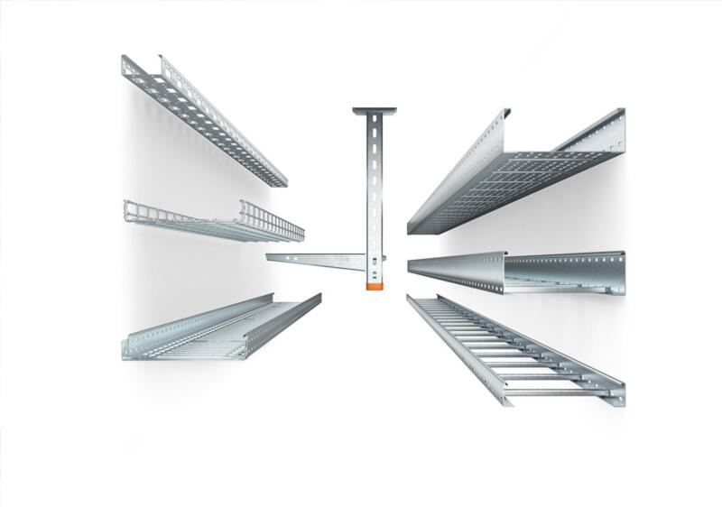
Summary
Closed, metal cable routing systems included in the equipotential bonding reduce the induced interference currents and interference voltages in a cable. These result due to electromagnetic interference fields. Compared with non-metallic variants or installation without cable routing systems, closed metallic cable routing systems offer the highest magnetic shield attenuation.
Perforated cable routing systems also offer a high magnetic shield attenuation, which, however, decreases with an increasing hole size.
Therefore, mesh cable trays and cable ladders only offer low magnetic shield attenuation. If open cable routing systems (without covers) are used, the magnetic shield attenuation decreases accordingly.
The table provides an overview of the magnetic shield attenuation of various versions of cable routing systems.
| Version of the cable routing system | Closed (with cover) | Open (without cover) |
|---|---|---|
| Without perforation/holes | 40 dB (99%) | 25 dB (94%) |
| 15% perforation/holes | 30 dB (97%) | 20 dB (90%) |
| 28% perforation/holes | 25 dB (94%) | 15 dB (82%) |
| Cable ladders | 18 dB (87%) | 11 dB (72%) |
| Mesh cable tray | 14 dB (80%) | 7 dB (55%) |
Additional contents
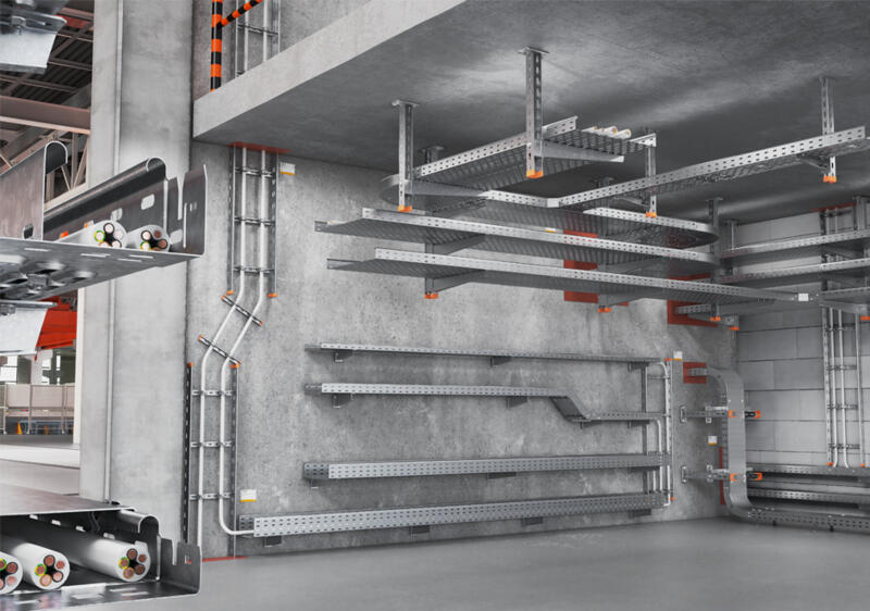
Cable support systems at a glance
Robust, safe, long-lasting – learn more about cable support systems, corrosion, surfaces and materials.
Finding the right cable support system
How do you choose the right cable support system for a planned installation? We will advise you on why cable volume and cable load are some of the important criteria.
Wind loads: What you have to take into account during planning
Wind can pose a real challenge during installation. Here, you will learn how to reliably secure cable support systems against wind loads.
IEC 61537:2006 – requirements for cable support systems
What requirements do cable support systems have to meet? Product standard IEC 61537:2006 sets out clear standards for load capacity, safety and labelling.
Tested quality – certificates, standards and test marks at a glance
From ISO to UL: Learn which certificates and test marks attest to the quality and safety of our cable tray systems, nationally and internationally.