Selection of the correct system
The proper sizing and selection of cable support systems is crucial for the operational safety and efficiency of an electrical installation. We show you how you can find the right system for your application. A variety of technical factors play a role, such as the cable volume, cable weight, the required useable cross-section and other application-specific requirements.
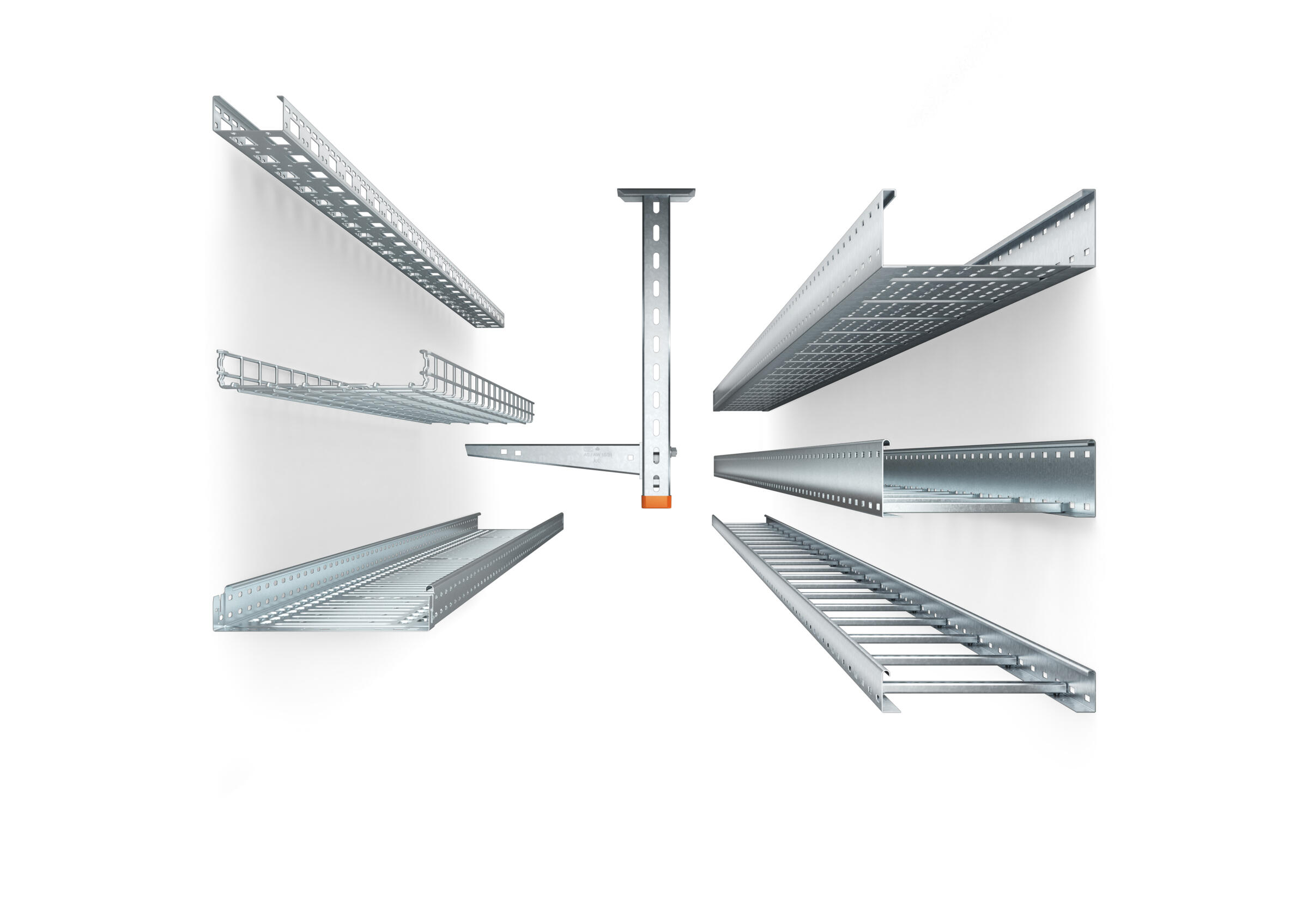
System application
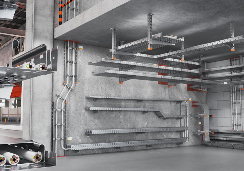
Cable support systems The cable tray is suitable for the universal routing of cables: from low-voltage cabling to power supplies, from data cables to telecommunications networks. The OBO portfolio offers a full product range with practical system components, enabling you to find the right solution for any challenge. Depending on the system, screwable or lockable cable trays with quick connection are available.
Mesh cable trays OBO mesh cable tray systems stand out through their high load capacity and good ventilation. They are suitable for the installation of power cables and cables in various areas of application, such as for IT cabling, telephone cabling and control cables. In addition, they are suitable for use in false ceilings and cavity floors.
Cable ladders The cable ladder systems from the OBO portfolio stand out through their high load capacity and good ventilation. This makes them particularly suited to the installation of power cables and cables with large cross-sections. They can be used universally and, due to the continuous rail and rung perforation, offer countless installation options. One example is the integrated fastening of cables on the rungs using OBO clamp clips.
Mounting systems: Mounting systems include the following product areas: universal systems, U support systems and I support systems. All the systems can, depending on the material and surface version, be used in interior and exterior areas.
Universal systems: Universal systems for cable support structures are used for small loads. They are suspended from the ceiling with threaded rods. Stand-off brackets allow raised floor mounting of cable trays, ladders and mesh cable trays.
U support systems: At OBO, U support systems for cable support structures comprise the light-duty US 3 system, the medium-duty US 5 system and the heavy-duty US 7 system. The different systems are designed for light, medium-weight and heavy loads. The U support systems can be used as ceiling suspension, floor stand-off or as construction profiles.
I support systems: I support systems for cable support structures are used to bridge large loads and support spacings, and to create complex section routes. The systems allow large support spacings of wide span systems or the multilayer arrangement of cable trays and cable ladder systems. The systems comprise I hanging supports, support brackets, head plates, I supports and I support connectors, as well as carrier lugs and mounting angles. The high load capacity of all the system components and the wide range of accessories permit the mounting of complex structures.
All the systems can, depending on the material and surface version, be used in interior and exterior areas.
FAQ – system selection
What standard lays out the requirements for cable support systems?
What general requirements apply for cable support systems and where are they laid out?
What test requirements apply to cable support systems?
How do cable support systems have to be labelled?
In which environments can OBO cable support systems be used?
Determine the cable volume
The term “cable” means a jacketed cable for the transmission of electrical energy and data. Cables are given according to their nominal cross-section. The external diameter and usable cross-section depend on their nominal cross-section and the number of individual wires contained in the cable. The diameter says little about the space requirements of a cable, as the arrangement can always cause certain air pockets and cavities. This means that, for simplicity, the squared space requirements are calculated using the formula (2r)².
Space requirements = (2r)² = diameter²
Example:
NYM-J 3 x 2.5: Cable diameter 9.50 mm
(9.50 mm)² = 90.25 mm²
Good to know: You will find the corresponding usable cable cross-sections in the data sheets from the respective cable manufacturers.
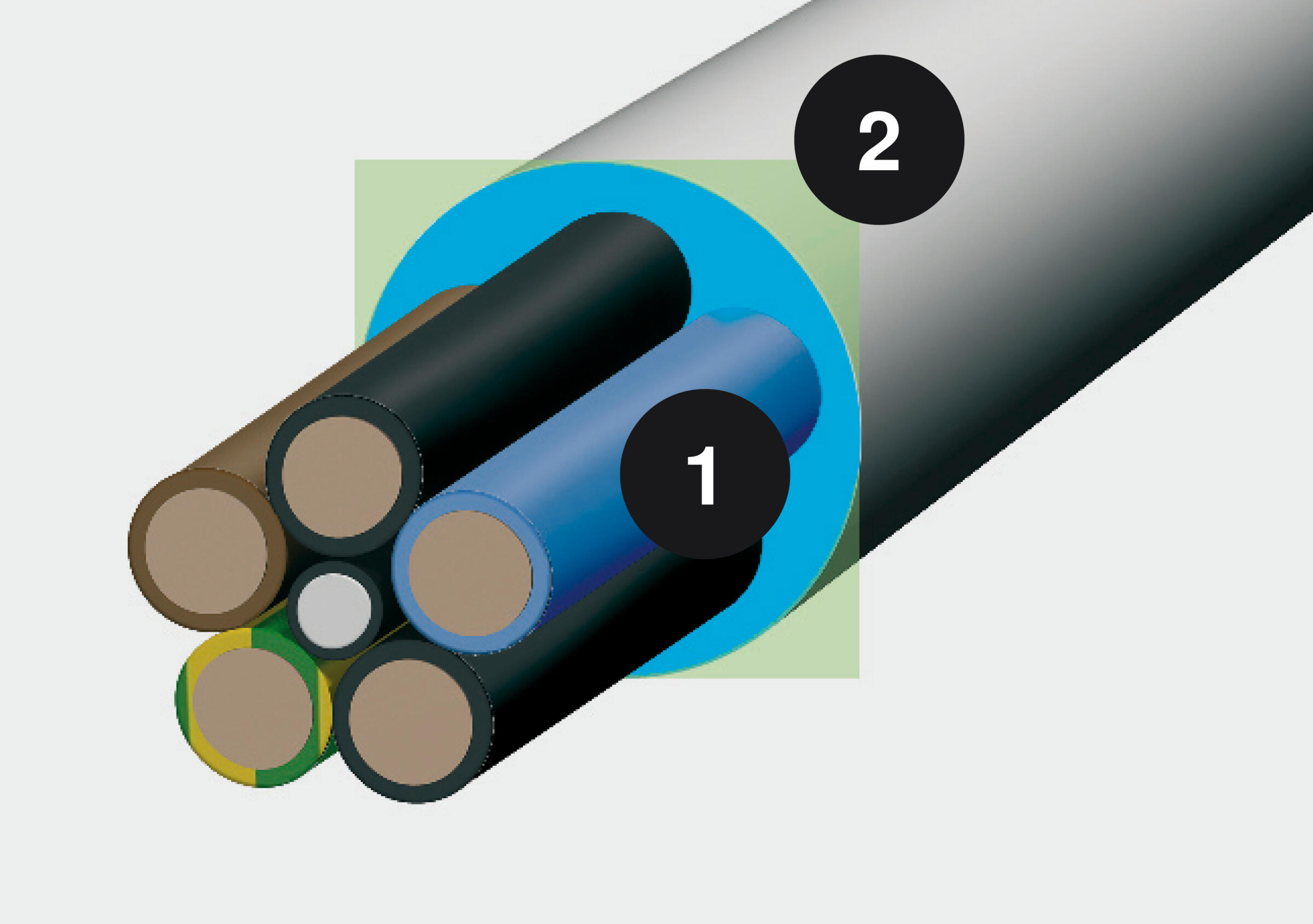
1 Diameter in mm
2 Space requirements in mm²
Calculating the cable load
The specifically occurring cable load is a value, which can be calculated with the help of the characteristic values of the available cable and the inclusion of the information offered in VDE 0639 Part 1 (Cable support systems).
The calculation of the specific cable load can be determined by dividing the weight of the cable (given in kg/m) by the usable cross-section of the cable (see above, given in mm²). This division is finally multiplied by the location factor 9.81 N/kg.
Spec. cable load = (cable load [kg/m])/(usable cross-section [mm2])*9.81 N/kg
This formula can be used to determine the specific cable load of each cable. This is an example for NYM-J 3x2.5:
Spec. cable load = (0.19 kg/m)/(90.25 mm2 )*9.81 N/kg = 0.021 N/(m*mm2)
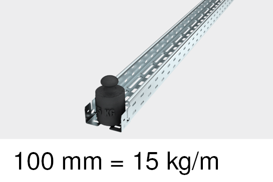
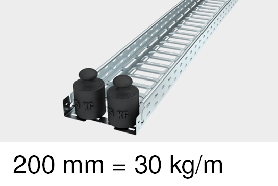
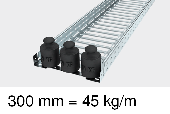
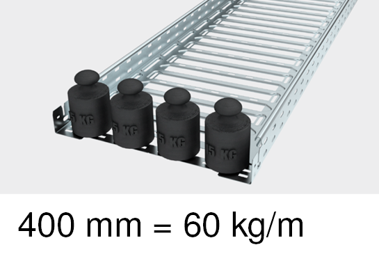
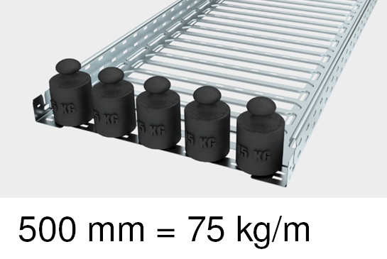
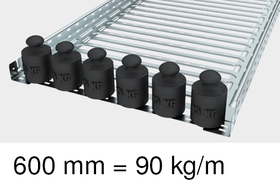
In VDE 0639, the heaviest listed cable has a specific cable load of 0.028 N/m*mm. This is an insulated heavy current cable NYY-J 4x95. Higher specific weights can only be achieved by cables with large cross-sections, which are less bendable and thus can support themselves better. On account of their larger diameter, they have a lower filling coefficient for the usable tray cross-section. As an alternative to calculating the cable load, the use of empirical values is also possible. Therefore, it can generally be assumed that a system of, for example, 60 mm rail height per metre of cable tray or cable ladder will produce a value of 15 kg per 100 mm width.
Determining the usable cross-section
The usable cross-section of a cable support system is aligned to the appropriate dimension. For simplicity, the area calculation using the cable support width and height can be used for rough planning. OBO also shows the usable cross-section of each cable support system in the catalogue.
Our overview gives an at-a-glance look at the usable cross-sections of the individual cable support system types. The differing structure of the systems mean that they also have different usable cross-sections. During dimensioning, we recommend a space reserve of approx. 30%.
Cable trays
Height [mm] | 35 | 60 | 85 | 110 |
|---|---|---|---|---|
Width [mm] | Usable cross-section [mm²] | |||
| 100 | 3,300 | 5,800 | 8,300 | 10,800 |
| 150 | 5,050 | 8,800 | 12,500 | 16,100 |
| 200 | 6,800 | 11,800 | 18,600 | 21,800 |
| 300 | 10,300 | 17,800 | 25,300 | 32,800 |
| 400 | - | 23,800 | 33,800 | 43,800 |
| 500 | - | 29,800 | 42,300 | 54,800 |
| 600 | - | 35,800 | 50,800 | 60,300 |
Cable ladders
Height [mm] | 60 | 110 |
|---|---|---|
Width [mm] | Usable cross-section [mm²] | |
| 200 | 9,800 | 18,000 |
| 300 | 14,800 | 27,000 |
| 400 | 19,800 | 36,000 |
| 500 | 24,800 | 45,000 |
| 600 | 29,800 | 54,000 |
Mesh cable trays
Height [mm] | 35 | 55 | 105 |
|---|---|---|---|
Width [mm] | Usable cross-section [mm²] | ||
| 100 | 3,500 | 4,000 | 8,200 |
| 150 | 5,250 | 6,300 | 13,000 |
| 200 | 7,000 | 8,700 | 17,500 |
| 300 | 10,500 | 12,900 | 26,800 |
| 400 | - | 17,500 | 36,300 |
| 500 | - | 22,000 | 45,900 |
| 600 | - | 26,500 | 55,400 |
Calculating the cable weight
DIN VDE 0639 P1 (Cable support systems) offers a formula for the calculation of a maximum approved cable load. The formula contains the specific cable load which was the subject of the previous chapters, as well as the usable cross-section of the cable support system.
Cable load (F) = (0.028 N)/(m*mm2)*Usable cross-section of the cable tray [mm²]
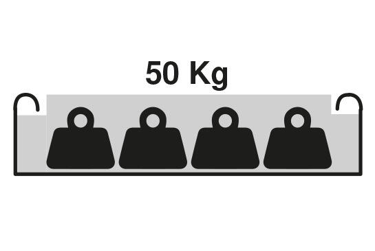
Example for a RKSM 60x300 cable tray
Cable load (F) = (0.028 N)/(m*mm2)*17,800 mm2 = 498.4 N/m = 0.5 kN/m ≈ 50 kg/m
As an overview, the following tables show the determined maximum occurring cable loads per dimension (rounded):
Cable trays
Height [mm] | 35 | 60 | 85 | 110 |
|---|---|---|---|---|
Width [mm] | Max. occurring cable load [kN/m ≈ 100 kg/m] | |||
| 100 | 0.09 | 0.16 | 0.23 | 0.30 |
| 150 | 0.14 | 0.25 | 0.35 | 0.45 |
| 200 | 0.19 | 0.33 | 0.52 | 0.61 |
| 300 | 0.29 | 0.50 | 0.71 | 0.92 |
| 400 | - | 0.67 | 0.95 | 1.23 |
| 500 | - | 0.83 | 1.18 | 1.53 |
| 600 | - | 1.00 | 1.42 | 1.69 |
Cable ladders
Height [mm] | 60 | 110 |
|---|---|---|
Width [mm] | Max. occurring cable load [kN/m ≈ 100 kg/m] | |
| 200 | 0.27 | 0.50 |
| 300 | 0.41 | 0.76 |
| 400 | 0.55 | 1.01 |
| 500 | 0.69 | 1.26 |
| 600 | 0.83 | 1.51 |
Mesh cable trays
Height [mm] | 35 | 55 | 105 |
|---|---|---|---|
Width [mm] | Max. occurring cable load [kN/m ≈ 100 kg/m] | ||
| 100 | 0.10 | 0.11 | 0.23 |
| 150 | 0.15 | 0.18 | 0.36 |
| 200 | 0.20 | 0.24 | 0.49 |
| 300 | 0.29 | 0.36 | 0.75 |
| 400 | - | 0.49 | 1.02 |
| 500 | - | 0.62 | 1.29 |
| 600 | - | 0.74 | 1.55 |
Selection of the cable support system
OBO offers load details including informative load tables, using which the suitable cable tray, mesh cable tray or cable ladder can be selected.
Finding the appropriate system for the cable load
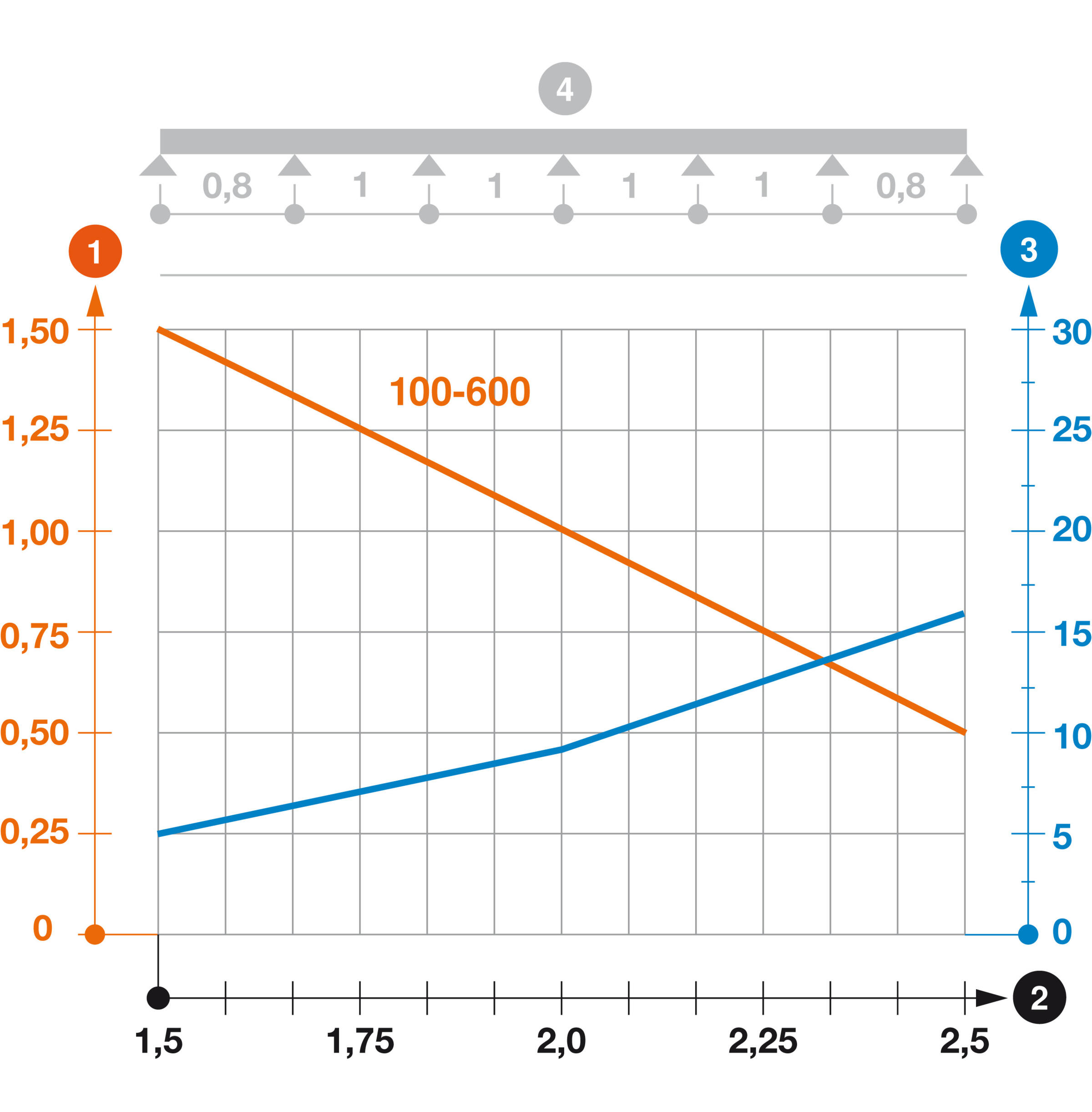
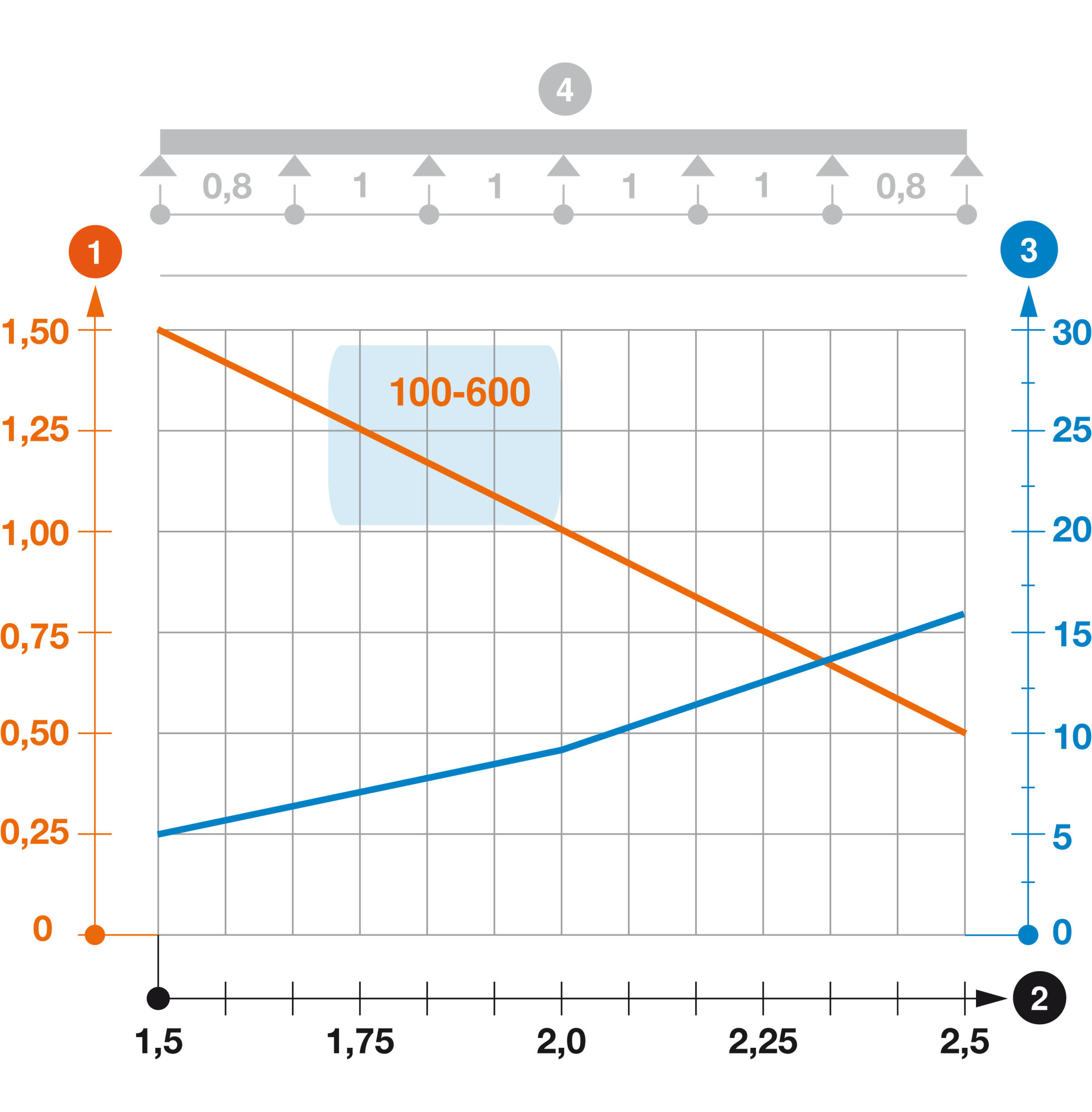
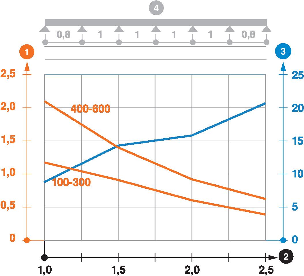
Load diagram, legend
1 = Load in kN/m without man load
2 = Support width in m
3 = Strut bending in mm
4 = Schematic diagram of the support widths for testing method
Orange line = Approved load according to support width for the different tray widths
Blue line = Rail bend according to support width
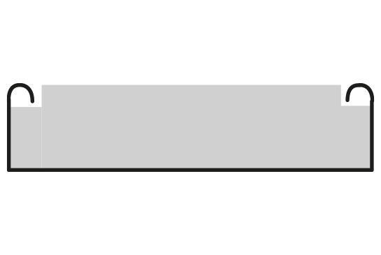
The testing process
The basic principles of the tests of OBO cable support systems come from VDE 0639 Part 1 and DIN EN 61537. The purpose of the tests is to determine the maximum load capacities for each component, depending on parameters such as component width, support spacing, etc. and to present this in a diagram to be included with each component. The area highlighted in blue in the above example schematises the experiment set-up with a variable support spacing (L) in the central area and a factor of 0.8 x L at the front and rear ends of the cable tray.
Load curves for selected cable tray or cable ladder widths
The load capacity of the cable trays according to the support width can be read off in the diagram using load curves – here, shown as an example for a cable tray with the tray widths 100 to 600 mm. It may occur that in the load curves, width differences must be made, allowing multiple curves to be visible simultaneously in the diagram. A key factor for the load capacity of the cable trays is (in addition to the support spacing and slant height) the material thickness, which varies according to type.
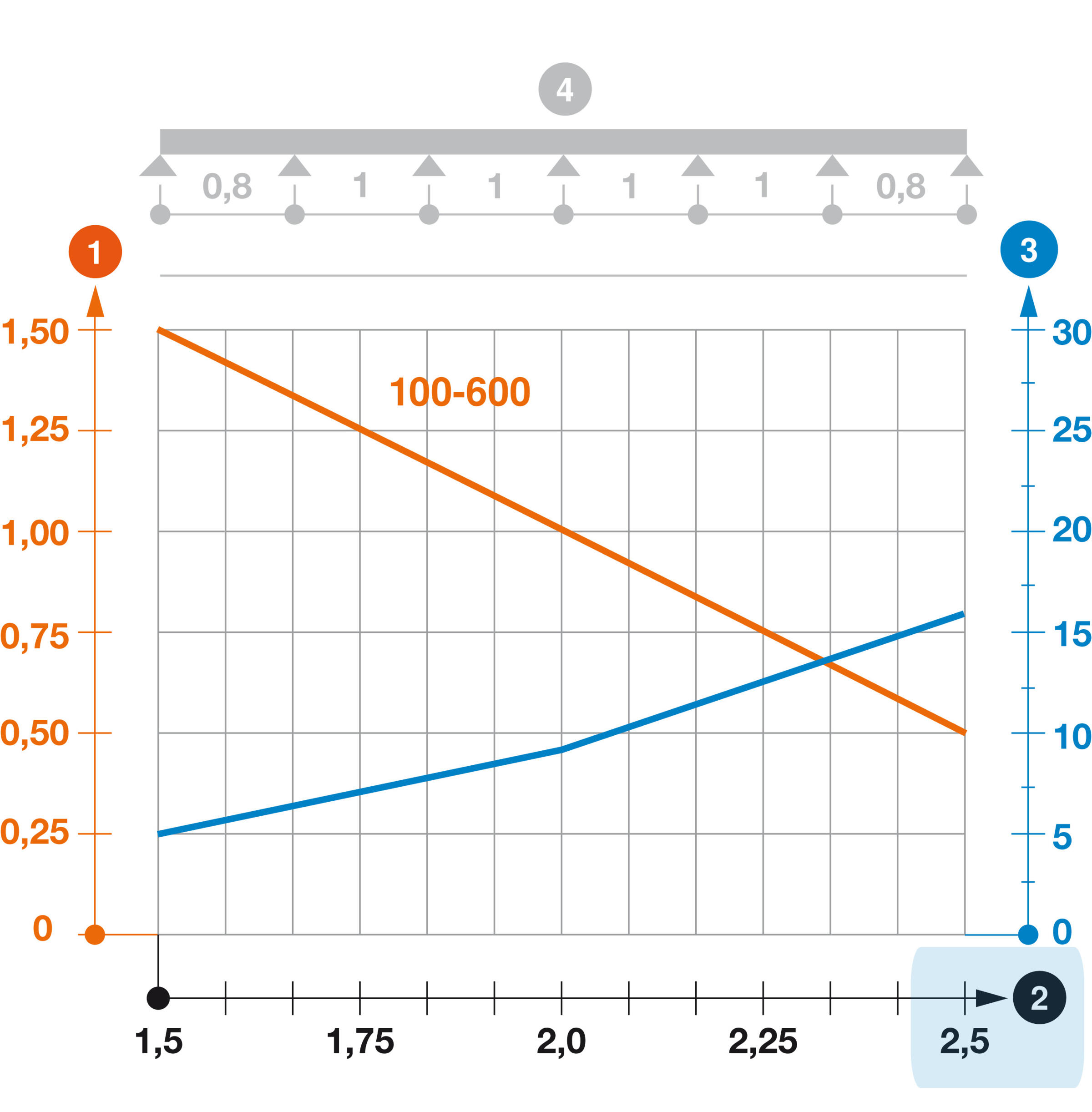
Possible spans
The theoretically possible spans for the cable tray can be read off on the axis at the foot of the table. Using the load curves, it is easy to read off to what extent the load capacity of the system falls as the support spacing grows. On all OBO cable support systems (with the exception of the wide span trays), we recommend not exceeding a support spacing of 1.5 m if possible.
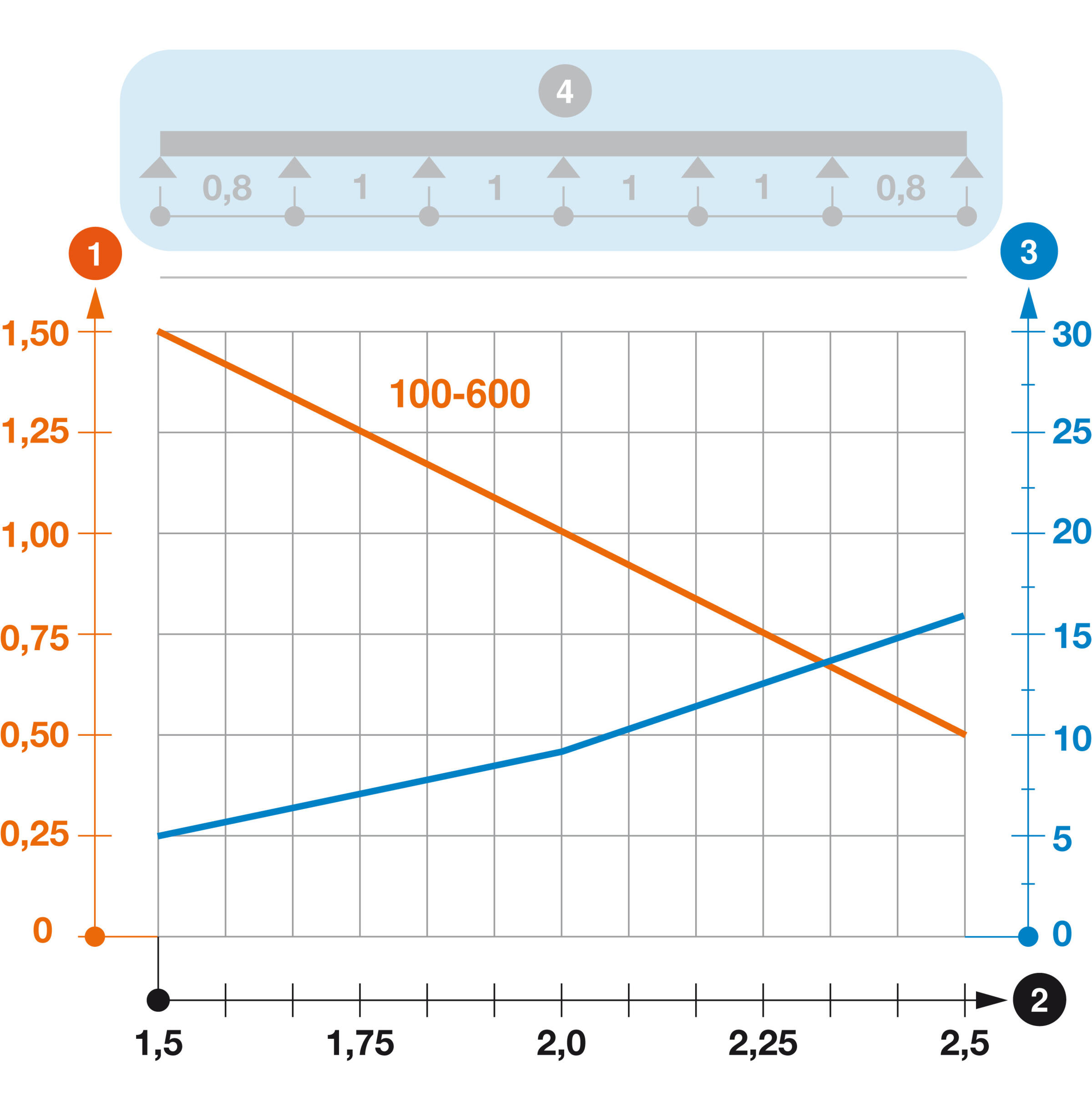
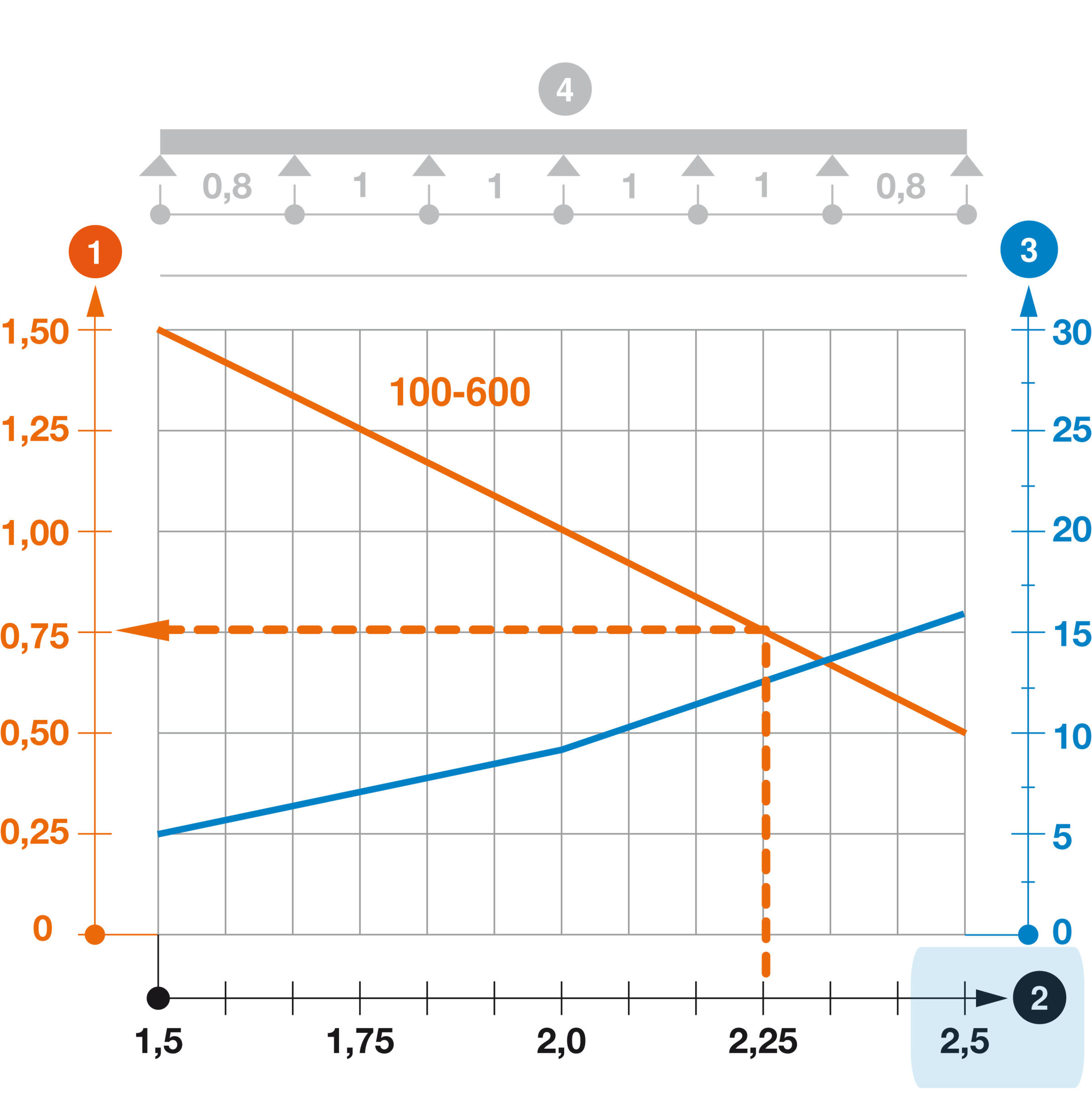
Load and span
Which load is possible at which support spacing? Which load is possible at which support spacing? You will find the answer in our diagram. In our example (with the blue background), a span of 2.25 m for the cable tray produces a maximum load capacity of 0.75 kN for each running metre of cable tray. Good to know: In this example, the volume of the cable tray may exceed the permitted load. For this reason, if at all possible do not exceed the recommended OBO standard support spacing of 1.5 m.
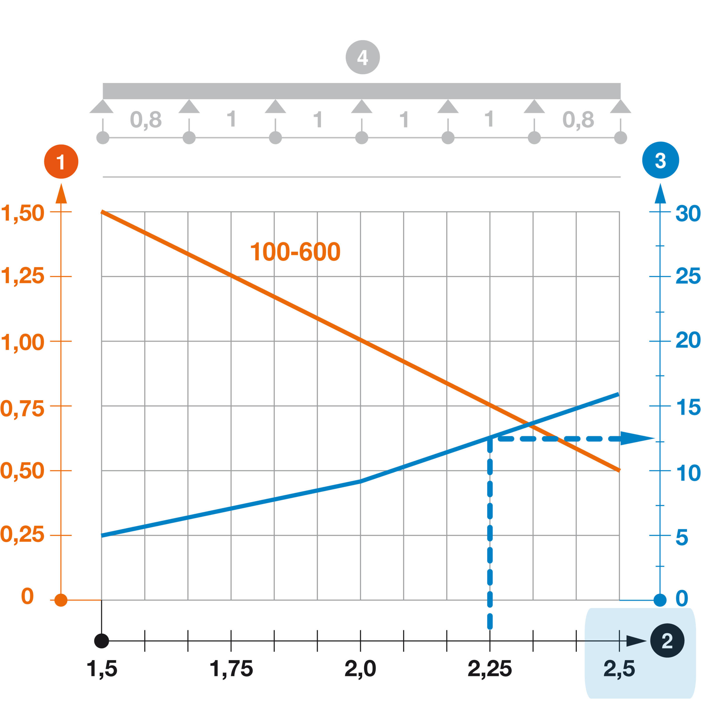
Strut bending
Above a certain level, the load on a cable tray causes the strut to bend. In our diagram, the blue curve (w) shows when this value has been reached in millimetres. The course of the blue curve clearly shows how quickly the cable tray will sag as the support spacing increases. In our example, the bend at a support spacing of 2.25 m is shown, here approximately 12 mm.
Load
| 1.0m kN/m | 1.5m kN/m | 2.0m kN/m | 2.5m kN/m | NEMA load class |
|---|---|---|---|---|---|
RKSM 610 FS | 1.2 | 0.9 | 0.6 | 0.4 | 8AA |
RKSM 615 FS | 1.2 | 1 | 0.6 | 0.4 | 8AA |
RKSM 620 FS | 1.2 | 1 | 0.55 | 0.4 | 8AA |
RKSM 630 FS | 1.2 | 1 | 0.55 | 0.4 | 8AA |
RKSM 640 FS | 2.1 | 1.35 | 0.8 | 0.6 | 8AA |
RKSM 650 FS | 2.1 | 1.35 | 0.8 | 0.6 | 8AA |
RKSM 660 FS | 2.1 | 1.4 | 0.8 | 0.6 | 8AA |
Load diagram, cable tray, type RKSM 60
1 = Approved cable tray/ladder load in kN/m without human load
2 = Support width in m
3 = Rail bend in mm at approved kN/m
4 = Load diagram for testing method
Orange line = Load curve with cable tray/ladder width in mm
Blue line = Rail bend curve depending on the support width
If necessary, the support spacing must be multiplied with the cable weight to be expected.
Pre-selecting the overall system
The following tables provide an overview of which fastening systems match which brackets.
Suspended support US 3
Hole Ø: Support | Bracket | Hole Ø: Bracket | Bolt | Item no. | Anchor | Item no. |
|---|---|---|---|---|---|---|
11 mm | MWA 12 11-13* | 11 mm | FRS 10x25 F 8.8 | 6407560 | BZ-U8-10-21/75 | 3498320 |
11 mm | AW 15 11-31 | 11 mm | FRS 10x25 F 8.8 | 6407560 | BZ-U10-10-30/90 | 3498334 |
11 mm | MWA 12 41 | 11 mm | DKS25 + SKS 10x90 F | 6416446 + 6418252 | BZ-U10-10-30/90 | 3498334 |
11 mm | AW 15 41 | 11 mm | DKS25 + SKS 10x90 F | 6416446 + 6418252 | BZ-U10-10-30/90 | 3498334 |
11 mm | AW 15 51-61 | 11 mm | Not possible with US 3 | - | - | - |
Suspended support US 5
Hole Ø: Support | Bracket | Hole Ø: Bracket | Bolt | Item no. | Anchor | Item no. |
|---|---|---|---|---|---|---|
11 mm | MWA 12 11-13* | 11 mm | FRS 10x25 F 8.8 | 6407560 | BZ-U8-10-21/75 | 3498320 |
11 mm | AW 15 11-31 | 11 mm | FRS 10x25 F 8.8 | 6407560 | BZ-U10-10-30/90 | 3498334 |
11 mm | AW 30 11 + 16 | 11 mm | FRS 10x25 F 8.8 | 6407560 | BZ-U10-10-30/90 | 3498334 |
11 mm | AW 30 21 + 31 | 13 mm | FRS 10x30 F + DIN 44011F | 6407579 + 6408729 | BZ12-15-35/110 | 3498350 |
11 mm | MWA 12 41 + AW15 41 | 11 mm | DSK 45 + SKS 10x90 F | 6416500 + 6418252 | BZ12-15-35/110 | 3498350 |
11 mm | AW 30 41 | 13 mm | DSK 45 + SKS 10x90 F | 6416500 + 6418252 | BZ12-15-35/110 | 3498350 |
Suspended support US 7
Hole Ø: Support | Bracket | Hole Ø: Bracket | Bolt | Item no. | Anchor | Item no. |
|---|---|---|---|---|---|---|
14 mm | MWA 12 11-41* | 11 mm | SKS 10x30 F + DIN 440 11F | 3160742 + 6408729 | BZ-U10-30/90 | 3498334 |
14 mm | AW 15 11-41 | 11 mm | SKS 10x30 F + DIN 440 11F | 3160742 + 6408729 | BZ-U10-30/90 | 3498334 |
14 mm | AW 30 11 + 16 | 11 mm | SKS 10x30 F + DIN 440 11F | 3160742 + 6408729 | BZ-U10-30/90 | 3498334 |
14 mm | AW 30 21 + 31 | 13 mm | FRS 12x30 F | 6406270 | BZ12-15-35/110 | 3498350 |
14 mm | AW 30 41-61 | 13 mm | DSK 61 + SKS 12x100 F | 6416519 + 6418295 | BZ12-15-35/110 | 3498350 |
14 mm | AW 55 21-41 | 13.5 mm | DSK 61 + SKS 12x100 F | 6416519 + 6418295 | BZ12-15-35/110 | 3498350 |
14 mm | AW 15 51-61 | 11 mm | DSK 61 + SKS 12x100 F + DIN 440 11 | 6416519 + 6418295 + 6408729 | BZ12-15-35/110 | 3498350 |
*Screw 6407560 is contained in the scope of delivery for the MWA/MWAG and MWA-M brackets.
Support and bracket combinations
Bracket arrangement, one-sided
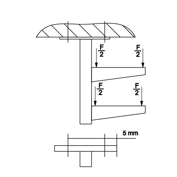
The basis for the recommendation is not the standard load capacity of the brackets, as tested according to DIN EN 61537, but rather the realistically occurring loads of a standard cable support system.
A maximum of 15 kg/m per 100 mm of section width and a support distance of 2.0 m are applied. In the final versions, the total load capacity of the system must always be taken into account, including the anchor load capacities. A spacer must always be used for support lengths > 600 mm and a bracket arrangement at the bottom end of the support.
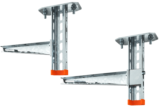
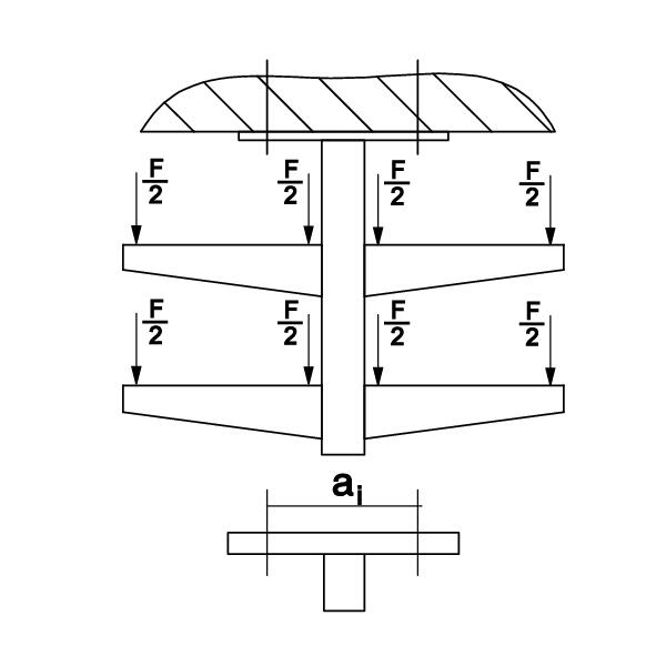
Bracket without (left) and with spacer (right).
Always mount the brackets as follows:
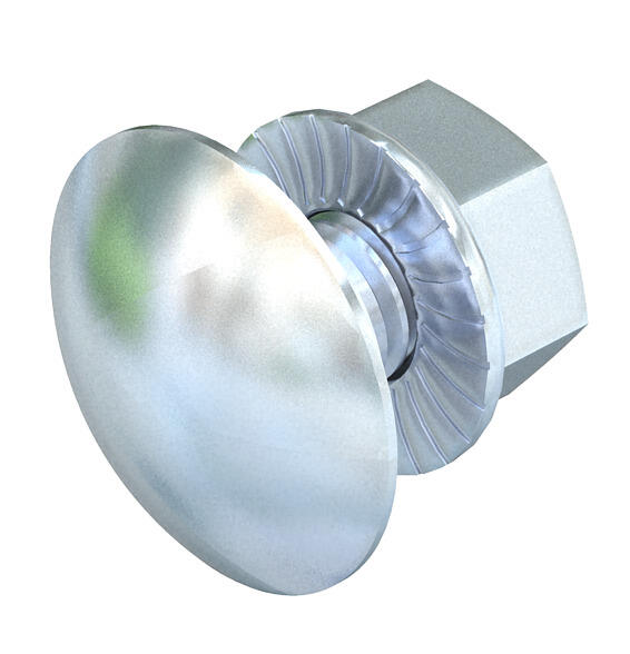
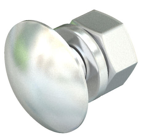
- Always mount the truss-head bolt on the support side
- Always mount the nut with washer on the bracket side
Select the mounting system according to the load capacity
OBO also offers matching load details including informative load tables – using which the suitable cable tray, mesh cable tray or cable ladder can be selected – for the mounting systems such as universal systems, U support systems, I support systems and trapezoidal systems.
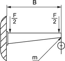
Characteristic load values
for anchors for AW 15 wall and support brackets – wall fastening
| Item on test | Force F (SWL) | Width B |
|---|---|---|
| AW 15 11 FT | 1.5 kN | 110 mm |
| AW 15 16 FT | 1.5 kN | 160 mm |
| AW 15 21 FT | 1.5 kN | 210 mm |
| AW 15 31 FT | 1.5 kN | 310 mm |
| AW 15 36 FT | 1.5 kN | 360 mm |
| AW 15 41 FT | 1.5 kN | 410 mm |
| AW 15 51 FT | 1.5 kN | 510 mm |
| AW 15 56 FT | 1.5 kN | 560 mm |
| AW 15 61 FT | 1.5 kN | 610 mm |
Deformation measuring point m | According to IEC 61537
Max. total load F = Cable weight + cable tray + bracket
Characteristic load values for anchors for AW 15 wall and support brackets – wall fastening
| Load [kN] | ||||
|---|---|---|---|---|
| Bracket width [mm] | 110 | 210 | 310 | 410 |
| Anchor type | ||||
| BZ-U 10-10-30/90 | 1.2 | 1.2 | 1.2 | 1.2 |
The load capacity values increase considerably when used in uncracked concrete.
The specified values are based on concrete of resistance grade C20/25.
Please comply with the installation conditions of the DIBt approval (anchors).
Characteristic anchor load values for US 3 K support
Single-sided load
| Max. load [kN] | ||||
| Bracket width [mm] | ||||
| Anchor type | 110 | 210 | 310 | 410 |
| BZ-U 8-10-21/75 | 2.00 | 1.50 | 1.15 | 0.90 |
| BZ-U 10-10-30/90 | 3.50 | 2.70 | 2.00 | 1.75 |
Characteristic anchor load values for US 3 K support
Double-sided load
| Max. load [kN] | ||||
| Bracket width [mm] | ||||
| Anchor type | 110 | 210 | 310 | 410 |
| BZ-U 8-10-21/75 | 3.75 | 3.25 | 2.8 | 2.50 |
| BZ-U 10-10-30/90 | 6.00 | 5.80 | 5.00 | 4.50 |
Max. load F total = Cable weight + cable tray + bracket + suspended support
The table values for the double-sided load take the existing axis distance ai = 10 cm into account. The load capacity values increase considerably when used in uncracked concrete. The specified values are based on concrete of resistance grades C20/25. Please comply with the installation conditions of the DIBt approval (anchors).
Final check of anchor system
The following tables on the anchoring depth of the anchors act as a guide for subsequent system inspection.
Standard anchoring depth
| Loads and characteristic values | Anchoring depth | Drill hole Ø | Drill hole depth | Clamping strength | Permitted load area, tension zone |
| mm | mm | mm | mm | kN | |
| M 8-100/165 | 46 | 8 | 60 | 100 | 2.4 |
| M 10-75/155 | 60 | 10 | 75 | 75 | 4.3 |
| M 10-100/180 | 60 | 10 | 75 | 100 | 4.3 |
| M 10-150/230 | 60 | 10 | 75 | 150 | 4.3 |
| M 12-15/110 | 70 | 12 | 90 | 15 | 7.6 |
| M 12-85/180 | 70 | 12 | 90 | 85 | 7.6 |
| M 12-105/200 | 70 | 12 | 90 | 105 | 7.6 |
| M 12-160/255 | 70 | 12 | 90 | 160 | 7.6 |
| M 16-15/135 | 85 | 16 | 110 | 15 | 11.9 |
Reduced anchoring depth
| Loads and characteristic values | Anchoring depth | Drill hole Ø | Drill hole depth | Clamping strength | Permitted load area, tension zone |
| mm | mm | mm | mm | kN | |
| M 8-100/165 | 35 | 8 | 49 | 111 | 2.4 |
| M 10-95/155 | 40 | 10 | 55 | 95 | 3.6 |
| M 10-120/180 | 40 | 10 | 55 | 120 | 3.6 |
| M 12-35/110 | 50 | 12 | 70 | 35 | 6.1 |
| M 12-105/180 | 50 | 12 | 70 | 105 | 6.1 |
| M 12-125/200 | 50 | 12 | 70 | 125 | 6.1 |
| M 16-35/135 | 65 | 16 | 90 | 35 | 9.0 |
You can also refer to the DIBT/ETA for the load values.
Mounting conditions
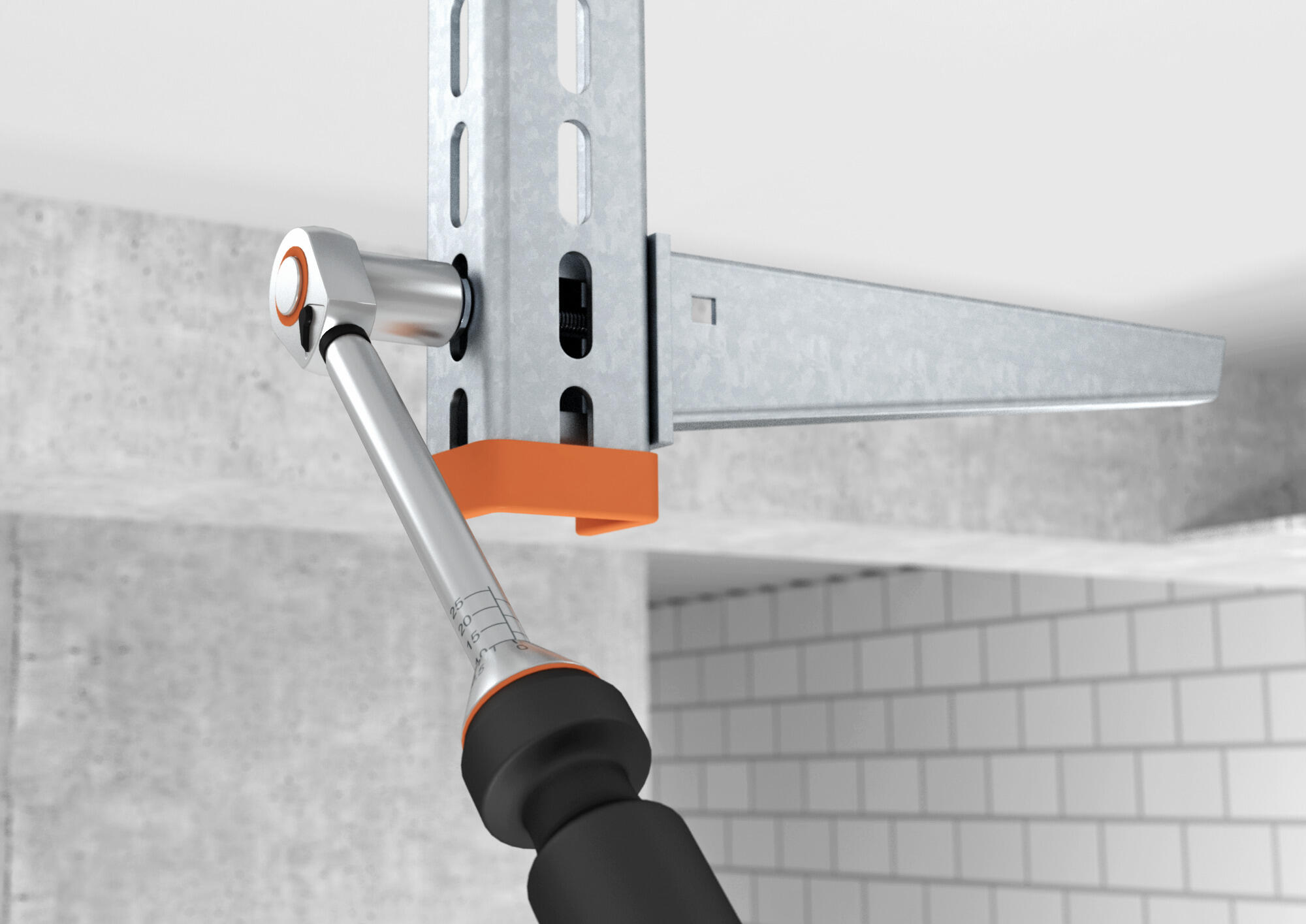
Tightening torques for bolts
Different tightening torques apply when mounting a cable support system. Please note that the specified torques are only intended as rough, non-binding guide values.
Tightening torques for steel bolts with metric thread
Thread | Tightness class 5.6 | Tightness class 8.8 |
|---|---|---|
Friction coefficient 0.14 | Friction coefficient 0.14 | |
| M6 | 4.80 Nm | 11.30 Nm |
| M8 | 11.60 Nm | 27.30 Nm |
| M10 | 23.10 Nm | 54.00 Nm |
| M12 | 40.40 Nm | 93.00 Nm |
| M14 | 64.70 Nm | 148.00 Nm |
| M16 | 100.70 Nm | 230.00 Nm |
Tightening torques for stainless steel bolts with metric thread
Thread | Resistance class 70 | Resistance class 80 |
|---|---|---|
Friction coefficient 0.20 | Friction coefficient 0.20 | |
| M6 | 9.70 Nm | 12.90 Nm |
| M8 | 23.60 Nm | 31.50 Nm |
| M10 | 46.80 Nm | 62.40 Nm |
| M12 | 81.00 Nm | 108.00 Nm |
| M14 | 129.00 Nm | 172.00 Nm |
| M16 | 201.00 Nm | 269.00 Nm |
Refer to the appropriate data sheets for the appropriate resistance classes of the products. These data sheets on our products are available to you for download.
OBO Construct – cable planning made easier than ever before
Our planning tool makes it possible: Within a project, you can calculate the cable assignment both for cable support systems and for underfloor ducts and trunking. Choose different assignment parameters and create custom cable types.
Additional contents
Cable support systems at a glance
Robust, safe, long-lasting – learn more about cable support systems, corrosion, surfaces and materials.
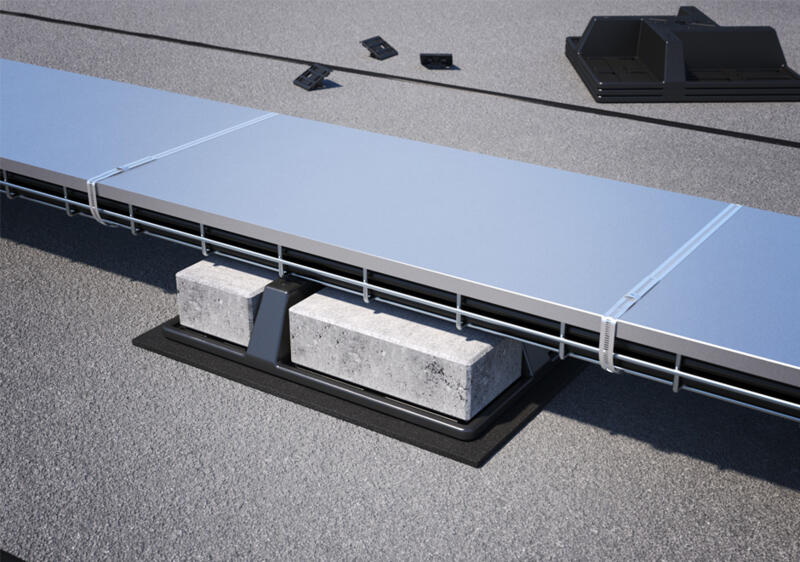
Wind loads: What you have to take into account during planning
Wind can pose a real challenge during installation. Here, you will learn how to reliably secure cable support systems against wind loads.
IEC 61537:2006 – requirements for cable support systems
What requirements do cable support systems have to meet? Product standard IEC 61537:2006 sets out clear standards for load capacity, safety and labelling.

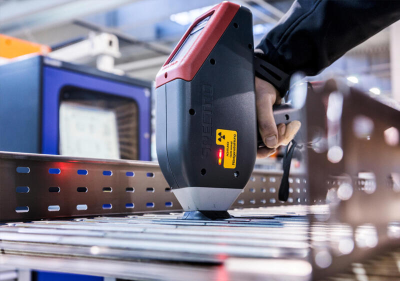
Tested quality – certificates, standards and test marks at a glance
From ISO to UL: Learn which certificates and test marks attest to the quality and safety of our cable tray systems, nationally and internationally.
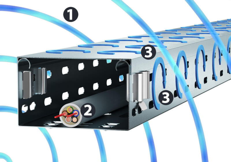
Protection against interference: EMC shield attenuation in cable support systems
Electromagnetic interference fields can cause entire systems to fail. Magnetic shield attenuation provided by properly installed cable routing systems offers protection.