Wind loads and wind load securing: Planning aids for cable support systems
Wind loads are a climatic force that affects structures and components. These forces can be both horizontal and vertical and have the potential to significantly impact the stability and integrity of buildings and engineering systems. The intensity of wind loads must be assessed separately by the installer for each construction project and depends on many factors. This includes, for example, the location, wind direction, surfaces, roof shape, and size and dimensions of the respective building.
Regions with similar conditions are defined as wind load zones in accordance with EN 1991-1-4. In conjunction with the corresponding National Annex, this standard applicable across Europe (also referred to as Eurocode) stipulates basic parameters for determining the effects of natural wind on buildings and engineering structures. The National Annexes contain provisions that go beyond the Eurocode rules, i.e. the provisions that were previously part of the national standards.

| Zone | Wind speed in m/s | Speed pressure in kN/m² |
| 1 | 22.5 | 0.32 |
| 2 | 25.0 | 0.39 |
| 3 | 27.5 | 0.47 |
| 4 | 30.0 | 0.56 |
Basic speeds and speed pressures
| Terrain category (TC) | Definition |
| Terrain category 1 | Open sea; lake with at least 5 km of open water in the wind direction and even, flat land without obstacles |
| Terrain category 2 | Terrain with hedges, individual farmsteads, buildings or trees, e.g. agricultural areas |
| Terrain category 3 | Suburbs, industrial or commercial areas and forests |
| Terrain category 4 | Urban areas in which at least 15% of the area is built up with buildings whose average height is higher than 15 m |
Terrain categories according to DIN EN 1991-1-4/NA
Use of covers outdoors: consider external mechanical forces
When installing covers outdoors, remember that they are subjected to external mechanical forces. This includes wind, snow and water. These additional loads are not covered by the international standard DIN EN 61537 and therefore have to be assessed separately for each construction project. The installer is responsible for this. Their assessment lays the foundation for additional safety measures that help ensure a permanently stable and safe electrical installation.
When using covers outdoors in areas that are subject to increased wind, there is a risk of the covers being lifted due to different pressure ratios. Suitable safety precautions have to be taken to prevent possible damage and minimise risks.
OBO offers a variety of solutions for additional support even in strong winds. The selection of a suitable system depends both on the specific construction project and the location. We’ll be happy to help.

Secure fastening even under an increased wind load
Different metal and tightening straps can be used for the weather-resistant fastening of covers and wind load securing. This ensures especially robust and resistant support, even under high wind loads. OBO offers the following solutions and more:
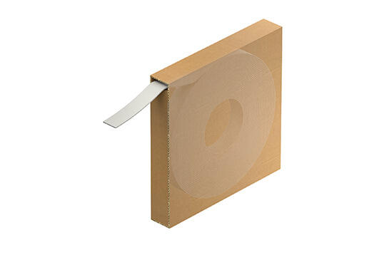
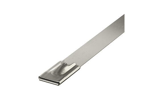
Tightening straps
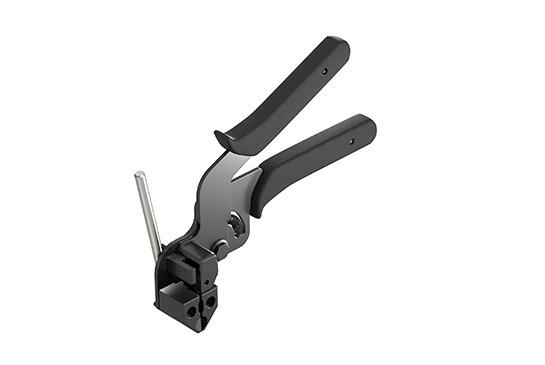
The SBR tightening strap made of galvanised steel, stainless steel or with an additional plastic coating is extremely robust and friction-resistant. It is tested for tensile strength (kN) according to the material strength and is available in various colours. Widths of 8 and 15 mm enable flexible adjustment to different cable trays, cable ladders and cable volumes. With the help of the matching SBV tightening strap locks and 576 spring chuck, the tightening straps can be installed simply, quickly and safely.
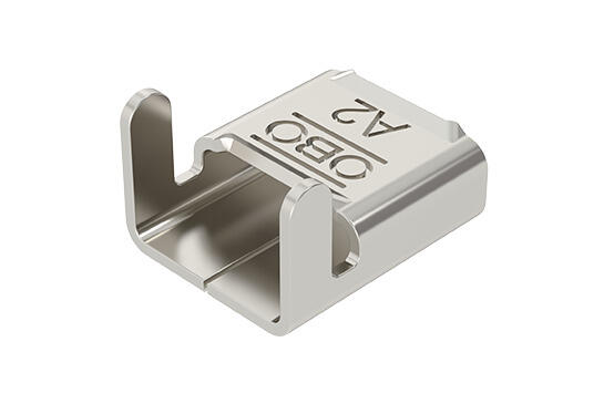
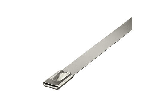
Metal strip clips
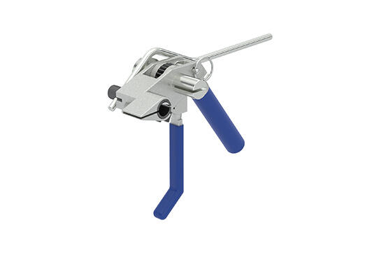
The MBS ribbon clips made of metal and with ball lock offer reliable fastening that withstands even high temperatures and adverse weather conditions. With widths of 7.9 and 12 mm as well as different fixed lengths, a wide range of applications is possible. The MBS-Z spring chuck with integrated cutter ensures precise, efficient installation.
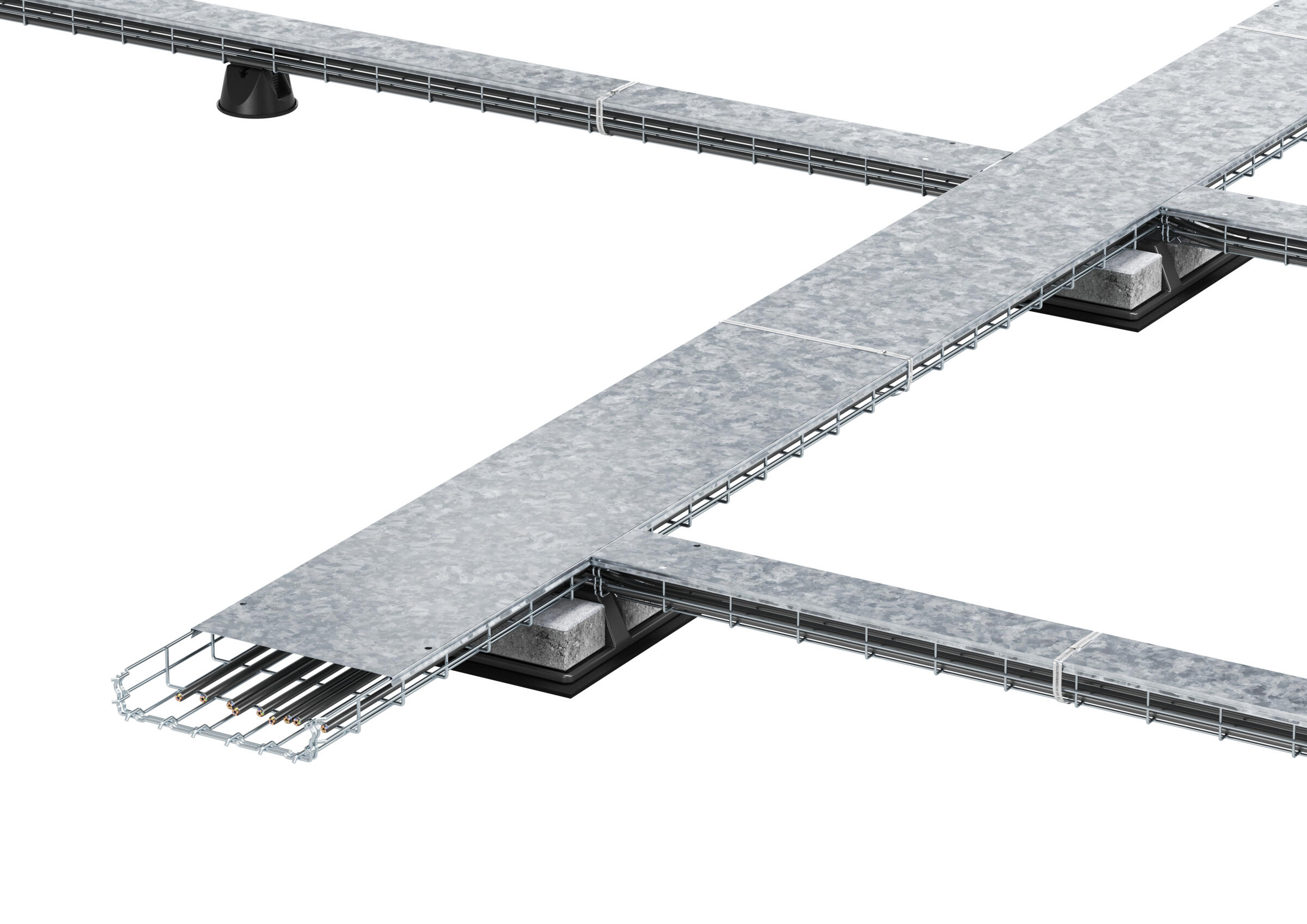
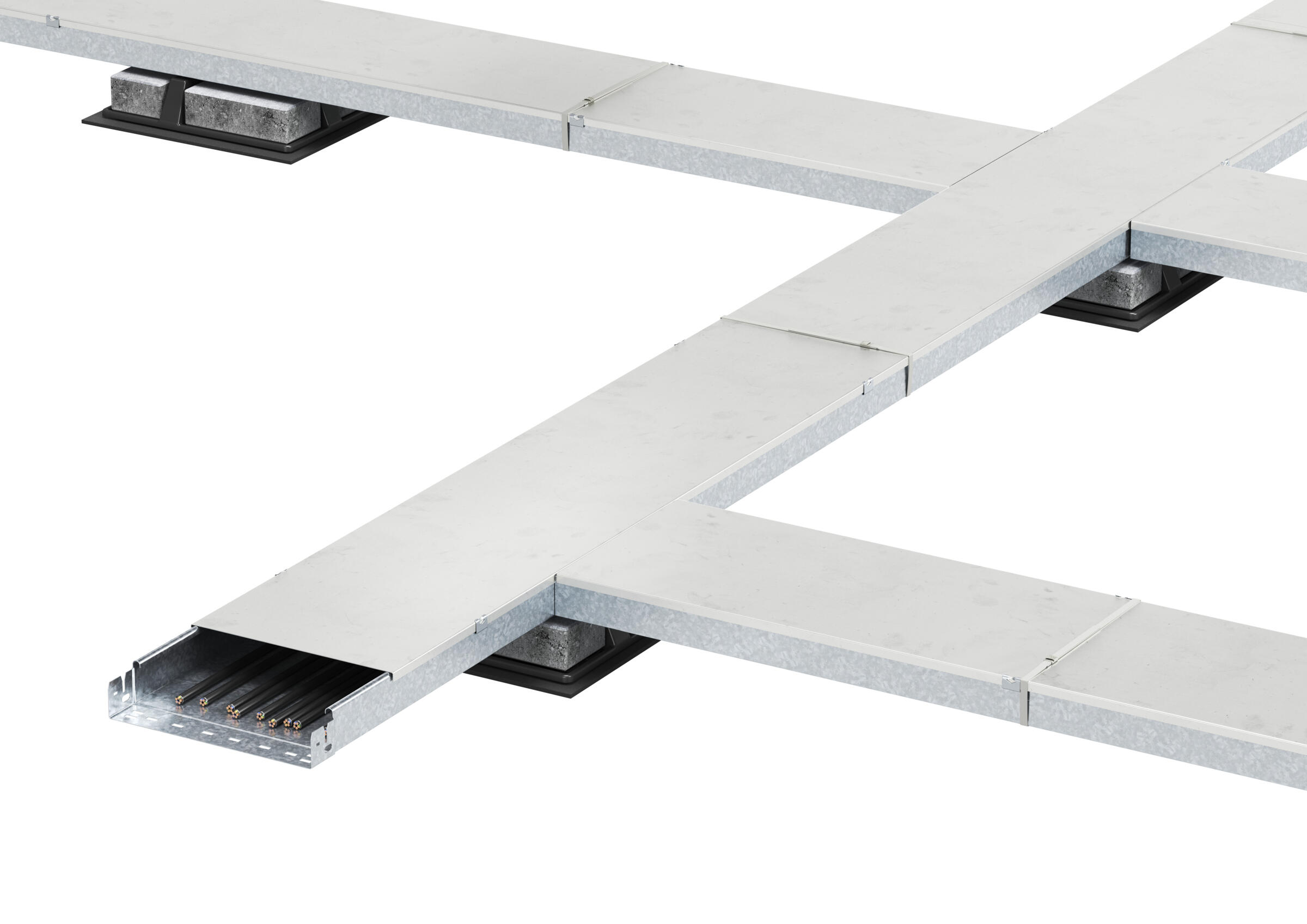
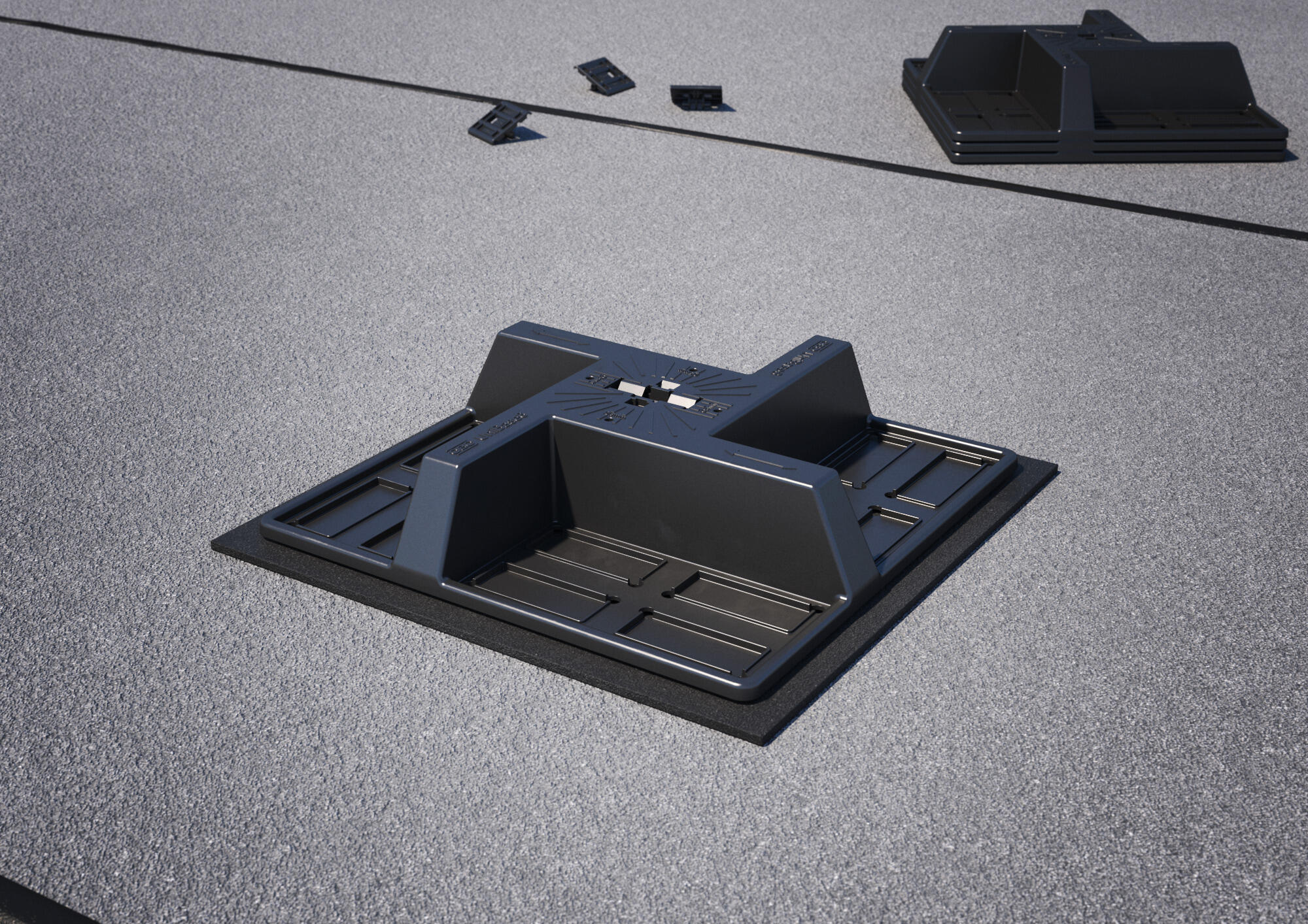
Installation principles, flat-roof mounting
Our figures show the flat-roof mounting of the Mesh cable tray GRM (left) and the flat-roof mounting of the unperforated (right).
Mounting aid for flat-roof mounting, GRM mesh cable tray
Placing UniBase 6
The UniBase 6 according to the roof assignment plan and place the UniBase BSM building protection mat under the stands as required. The maximum support spacing between the stands is 1.5 m.
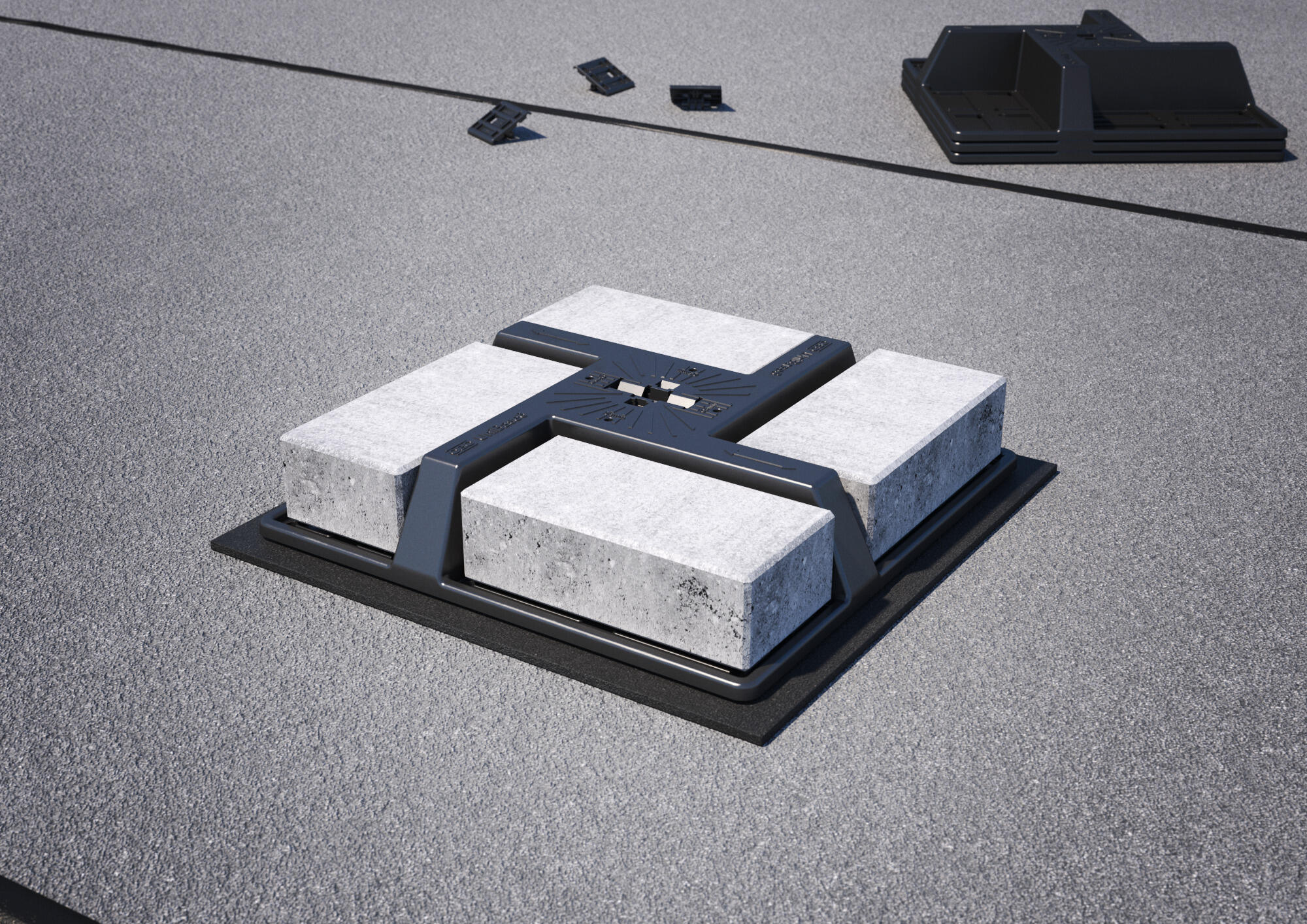
Ballasting UniBase 6
The stand UniBase 6 is weighed down using standard blocks of size (length x width x height) 10 x 20 x 6 cm.
Placing the GRM mesh cable tray
The Mesh cable tray GRM is fastened to the UniBase 6 universal stand without screws using the type 165 MBG HGRM adapter.
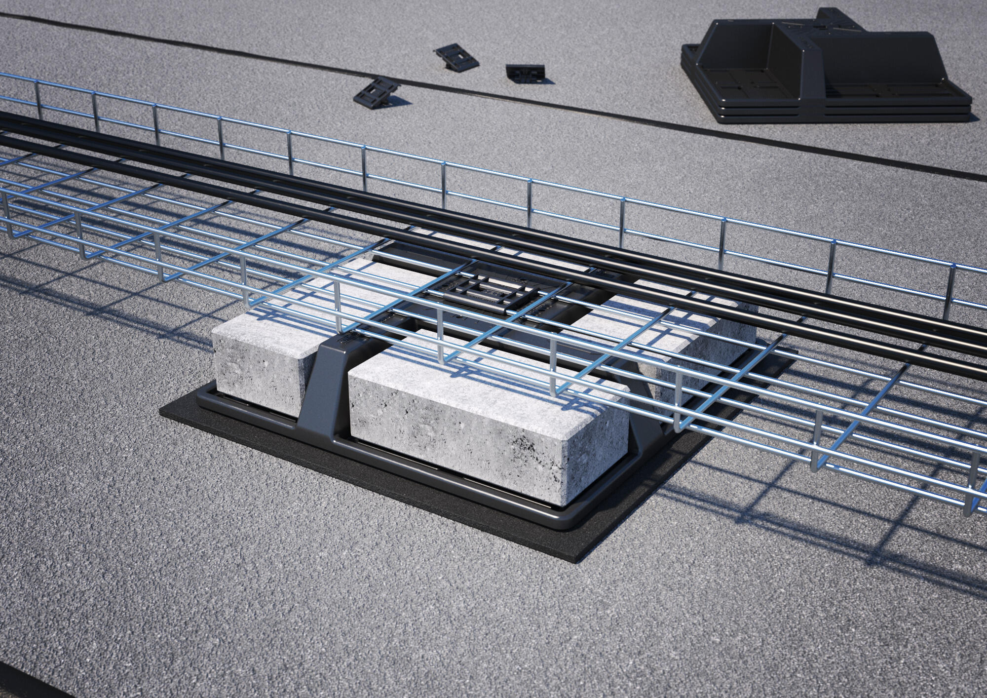
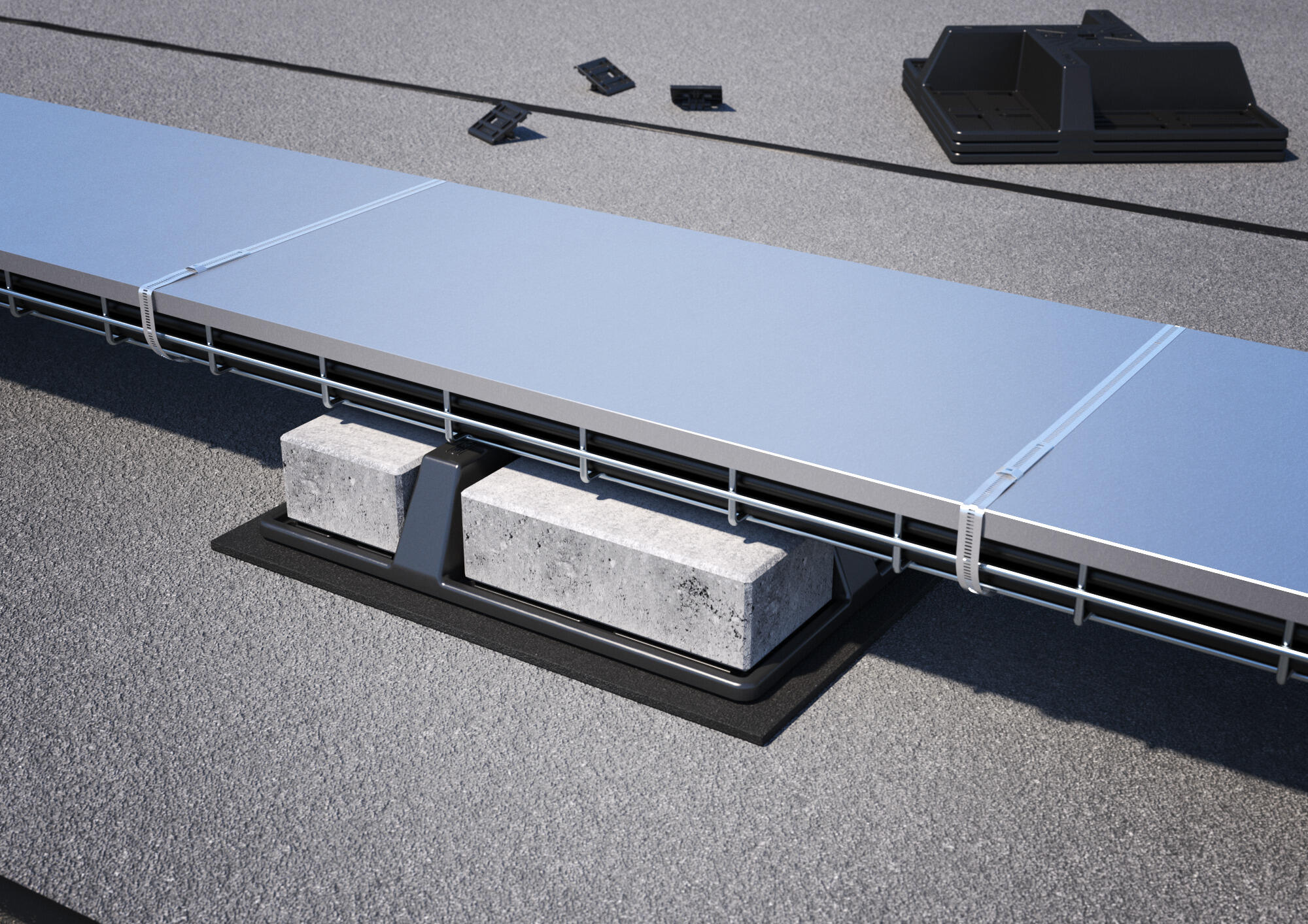
Mounting and fixing the DGRR cover
The Mesh cable tray cover DGRR lock to the mesh cable tray and with the Metal strip clips MBS cable clamps.
Example static calculation, cable routing on the roof
Basis of calculation
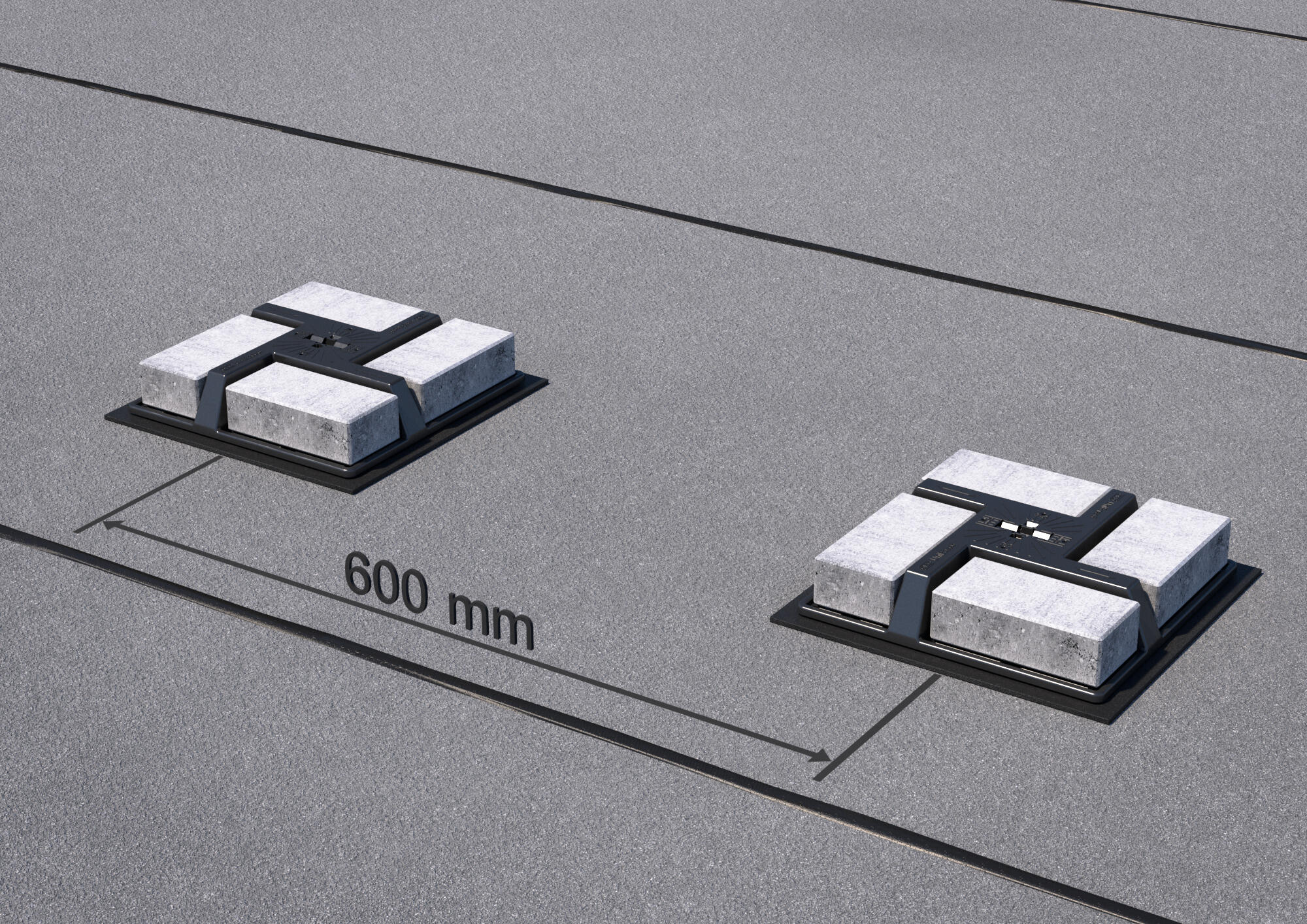
UniBase spacing
When installing cable support systems, for example on the UniBase universal stand, make sure that the support surface corresponds to the full width of the installed system. This ensures an even load distribution and increases stability against wind loads. In the following example static calculation, the spacing between the individual UniBase units is 0.6 metres.
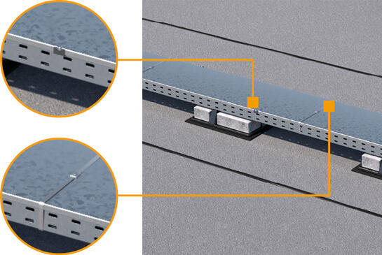
Number of cover clamps
At least 6 cover clamps should be mounted for each 3 metres of cover.
Metal strip clip spacing
The following is recommended for the spacing between the metal strip clips: Insert three clips per cover at 500, 1,500 and 2,500 mm.
System components used
| Item no. | Type | Designation |
|---|---|---|
| 5403391 | UniBase 6 | Universal stand ballasting, blocks up to 6 cm |
| 6047655 | RKSM 630 FT | RKSM Magic cable tray, with quick connector |
| 3191032 | OTSP 6.0x40 A4 | Chipboard screw, panhead, TX 25 |
| 6052656 | DRLU 300 DD | Unperforated cover, for cable tray and cable ladder |
| 6052810 | DK DRLU A2 | Cover clamp, for unperforated covers |
| 7203111 | MBS 100 A2 | Strip clip |
Formula for proof of stability (sliding + lifting):
Wh x γQ ≤ (Gstab x γstab-Wvh x γQ ) x μ
Designations
Wh Characteristic wind load, horizontal
Wvh Characteristic wind load, vertical for proof of lifting
Gstab Stabilising weight forces
YQ Partial safety factor for wind load
Ystab Partial safety factor for stabilising forces
µ Coefficient of friction
Calculate the horizontal wind force on the cable tray
First, the wind pressure applied horizontally to the side wall of the cable tray is calculated. The pressure is calculated by multiplying the wind gust velocity pressure, the side height, the force coefficient, the safety factor and the block spacing.
Wh1 x yQ = 0.5 kN/m2 (wind gust velocity pressure) x 60 mm (side height) x 1.0 (force coefficient) x 1.2 (safety) x 0.6 m (UniBase spacing) = 21.6 N
Calculate impact on the ballast block
To calculate the impact of the wind load on the ballast block, the block width/height is multiplied by the wind gust velocity pressure, a force coefficient and the safety factor.
Wh2 x γQ = 372 mm (block width) x 80 mm (block height) x 0.5 kN/m2 (wind gust velocity pressure) x 2.1 (force coefficient) x 1.2 (safety) = 37.5 N
Calculate system weight
The total system weight, including cable tray, cover and ballast block, is calculated taking the gravitational acceleration and safety factor into consideration.
Gstab x γstab = (6.12 kg/m (tray + cover) x 0.6 m (block spacing) + 10 kg (block weight)) x 9.81 m/s2 (gravitational acceleration) x 0.9 (safety) = 120.7 N
Determine the lifting load
To determine the lifting load, first the length exposed to wind is calculated from the block spacing and block width. Multiplying these values results in the area with wind load. Together with the gust velocity pressure, force coefficient and safety factor, this results in the lifting wind load.
Wvh x γQv = (0.6 m (block spacing) – 372 mm (block width)) x 300 mm (tray width) x 0.5 kN/m2 (wind gust velocity pressure) x 0.5 (vertical force coefficient) x 1.2 (safety) = 20.5 N
Proof of stability
First, the sum of the horizontal wind forces is determined. The system weight minus the previously determined lifting load with the coefficient of friction results in the maximum possible stabilising force. This determines whether stability is ensured.
Wh1 x γQ + Wh2 x γQ ≤ (Gstab x γstab – Wvh x γQv) x µ
21.6 N + 37.5 N < (120.7 N – 20.5 N) x 0.6 (coefficient of friction µ)
59.1 N < 60.1 N ➨ Proof provided
Example of national standards for wind and snow loads
General effects – wind loads | |
|---|---|
| Europe: | EN 1991-1-4 |
| Germany: | DIN EN 1991-1-4 |
| Belgium: | NBN EN 1991-1-4 |
| Austria: | ÖNORM B 1991-1-4 |
| The Netherlands: | NEN-EN 1991-1-4 |
| Switzerland: | SIA 261 |
| Spain: | CTE DB SE-AE |
| USA: | ASCE/SEI 7-16; ASCE/SEI 7-22 |
| India: | IS 875-3 |
General effects – snow loads | |
|---|---|
| Europe: | EN 1991-1-3 |
| Germany: | DIN EN 1991-1-3 |
| Belgium: | NBN EN 1991-1-3 |
| Austria: | ÖNORM B 1991-1-3 |
| The Netherlands: | NEN-EN 1991-1-3 |
| Switzerland: | SIA 261 |
| Spain: | CTE DB SE-AE |
| USA: | ASCE/SEI 7-16; ASCE/SEI 7-22 |
| India: | IS 875-4 |
Additional contents
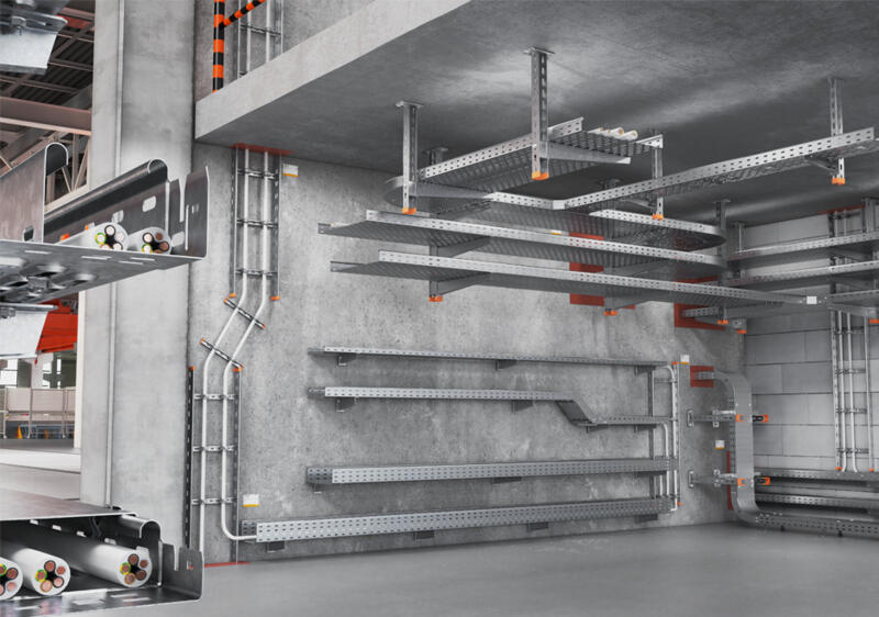
Cable support systems at a glance
Robust, safe, long-lasting – learn more about cable support systems, corrosion, surfaces and materials.
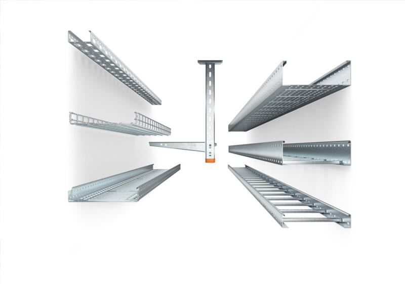
Finding the right cable support system
How do you choose the right cable support system for a planned installation? We will advise you on why cable volume and cable load are some of the important criteria.
IEC 61537:2006 – requirements for cable support systems
What requirements do cable support systems have to meet? Product standard IEC 61537:2006 sets out clear standards for load capacity, safety and labelling.

Tested quality – certificates, standards and test marks at a glance
From ISO to UL: Learn which certificates and test marks attest to the quality and safety of our cable tray systems, nationally and internationally.
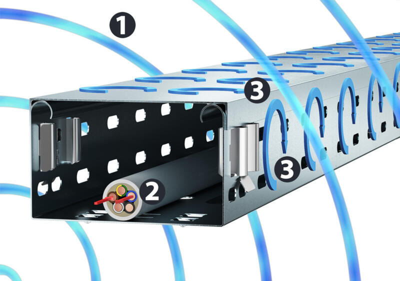
Protection against interference: EMC shield attenuation in cable support systems
Electromagnetic interference fields can cause entire systems to fail. Magnetic shield attenuation provided by properly installed cable routing systems offers protection.